Cutting insert and toolholder for holding the same

a toolholder and cutting insert technology, applied in the field of metalworking operations, can solve the problems of excessive tip-to-tip length of a particular standard cutting insert used for tuning operations, inconvenient use, and insufficient support of one insert optimally

Inactive Publication Date: 2005-01-27
KENNAMETAL INC
View PDF10 Cites 22 Cited by
  • Summary
  • Abstract
  • Description
  • Claims
  • Application Information

AI Technical Summary

Benefits of technology

[0010] A cutting insert for metalworking operations is comprised of an insert body having a top surface and a bottom surface defining sides therebetween and a core having two pairs of core sides. Top edges are defined at the intersection of the top surface with the sides, and bottom edges are defined at the intersection of the bottom surface with the sides. Each pair of core sides has a first core side and a second core side, wherein the top edges of these core sides form a core angle with one another. When viewed in plan, the top edge of the first core side of one pair is parallel to the top ed

Problems solved by technology

As a result, any one insert may not be supported optimally because portions of the toolholder pocket have been recessed and carved out to accommodate cutting inserts of other shape

Method used


Image

  • Cutting insert and toolholder for holding the same
  • Cutting insert and toolholder for holding the same
  • Cutting insert and toolholder for holding the same

Examples


Embodiment Construction

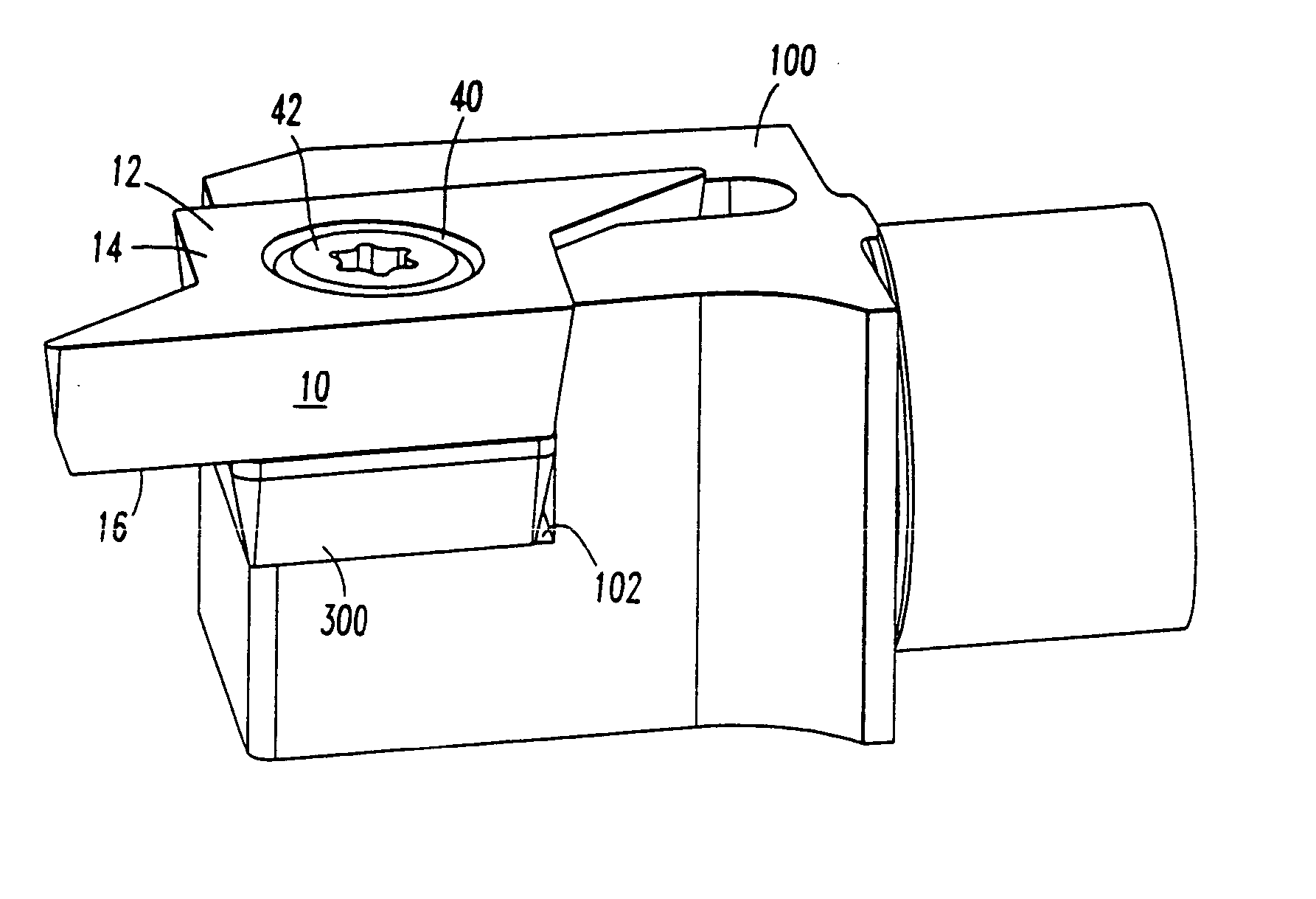
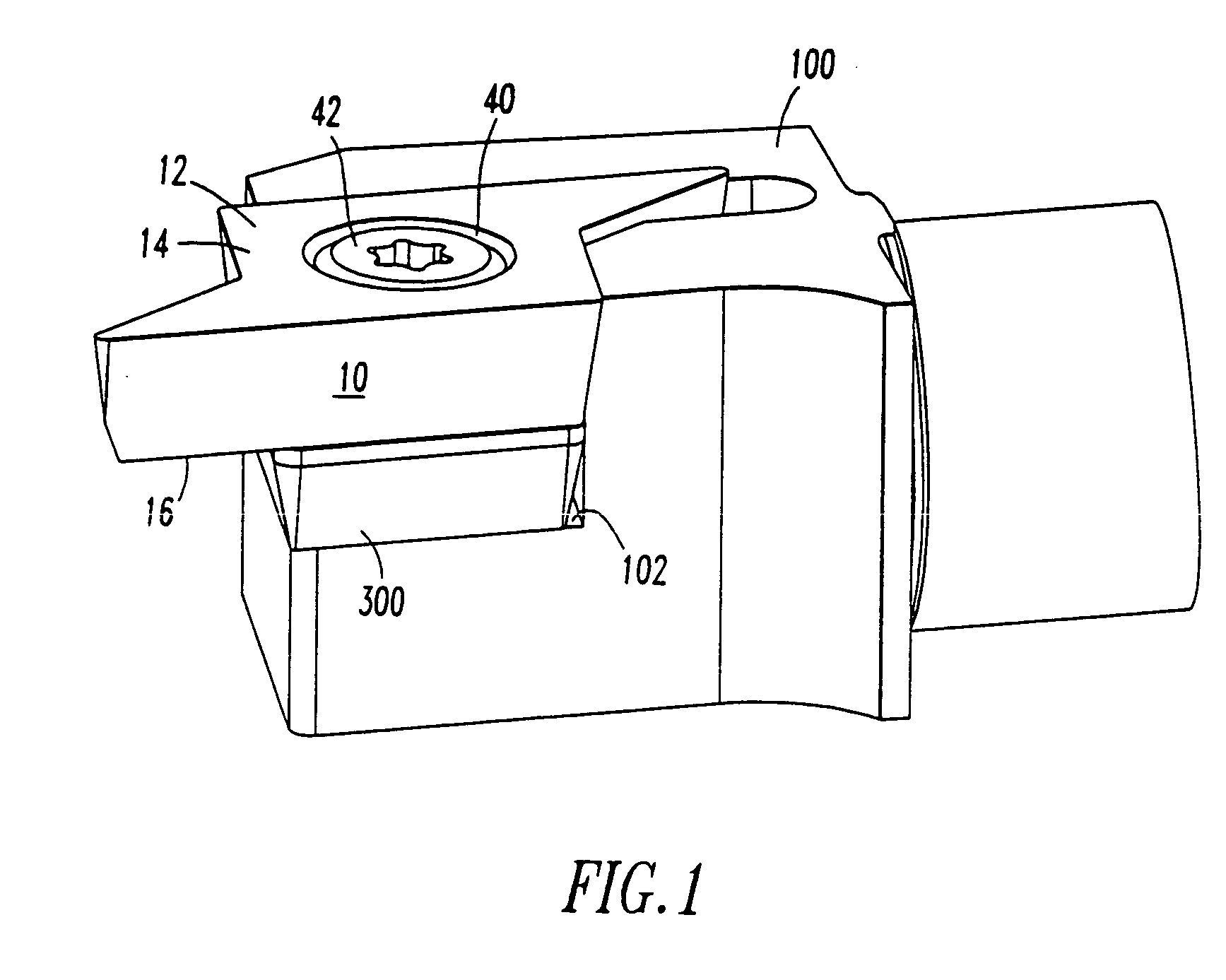
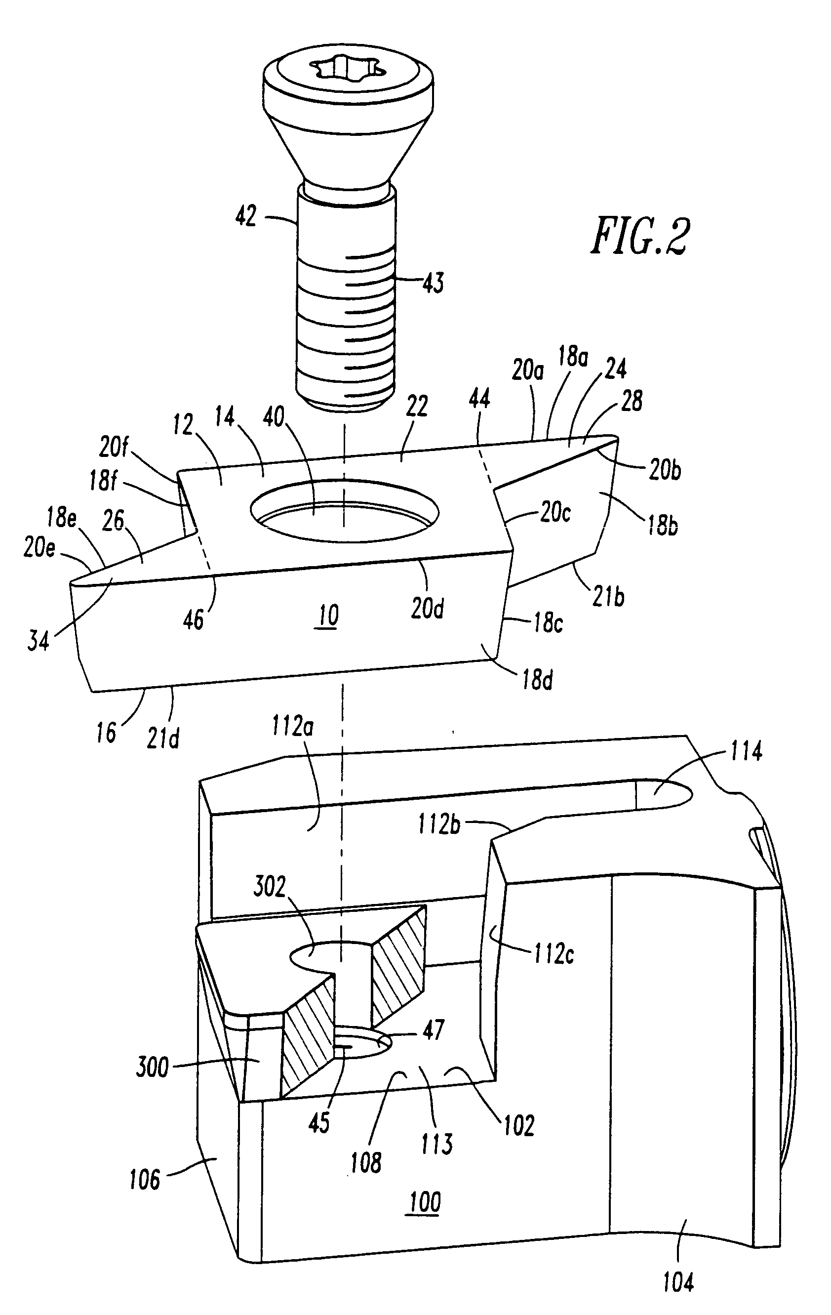
[0023]FIG. 1 illustrates a perspective view of a cutting insert 10 mounted within a toolholder 100 in accordance with the subject invention. FIG. 2 illustrates an exploded view of these same elements and FIGS. 1 and 2 will be discussed simultaneously.

[0024] The unique shape of the cutting insert 10 makes possible the introduction into a common toolholder of mounting one of a plurality of similar cutting inserts which, as will be seen, have a common core, but different cutting portions.

[0025] The cutting insert 10 is further illustrated in FIGS. 3A and 3B. The cutting insert 10 may be utilized for metalworking operations and has an insert body 12 with a top surface 14 and a bottom surface 16 defining sides 18a-18f therebetween, comprised of tip sides and core sides.

[0026] Top edges 20a-20f are defined at the intersection of the top surface 14 with the sides 18a-18f. Bottom edges are defined at the intersection of the bottom surface 16 with the sides 18a-18f. Bottom edges 21a and 2...


PUM

PropertyMeasurementUnit
Angleaaaaaaaaaa
Angleaaaaaaaaaa
Angleaaaaaaaaaa

Abstract

A cutting insert for metalworking operations has an insert core with a pair of cutting portions having cutting tips extending therefrom such that a toolholder having a pocket to accept such a core is suitable to accept different cutting inserts having a common core plus different cutting portions. As a result, for example, an 80° diamond, a 55° diamond and a 35° diamond cutting insert may all be utilized within a common toolholder. The invention is also directed to a toolholder that will accept such a variety of cutting inserts.

Description

BACKGROUND OF THE INVENTION [0001] 1. Field of the Invention [0002] The invention is directed to tooling for metalworking operations and, more particularly, directed to cutting inserts and the toolholder for holding such inserts during metalworking operations, such as turning. [0003] 2. Description of Related Art [0004] In turning operations, one of the primary criteria for selecting an appropriate insert is the required nose angle. The nose angle is defined at the cutting point in a cutting portion of the insert made up of two straight lines meeting at that point. There are turning inserts referred to as 80° diamonds, 55° diamonds and 35° diamonds, whereby these numerical values define the angle the two sides form with the cutting point. Typically, these inserts are symmetric with two opposing cutting regions. These inserts may also be indexable. [0005] In the past, each cutting insert having a different nose angle would require a dedicated toolholder having a pocket conforming to ...

Claims


Application Information

Patent Timeline
IPC IPC(8): B23B27/16B23B27/14
CPCB23B27/1614B23B2200/0423B23B2200/323Y10T407/2274B23B2205/16Y10T407/23B23B2205/12
Inventor ERICKSON, ROBERT A.ALEXANDER, WILLIAM M. IV
Owner KENNAMETAL INC
Why Eureka
Try Eureka