Charger for cellular phone

a cellular phone and charger technology, applied in the field of chargers, can solve the problems of inability to charge a cellular phone via a prior charger, and achieve the effect of more convenien

Inactive Publication Date: 2005-02-03
INVENTEC APPLIANCES CORP
View PDF5 Cites 43 Cited by
  • Summary
  • Abstract
  • Description
  • Claims
  • Application Information

AI Technical Summary

Benefits of technology

The technical effect described this new charger solves problems with previous designs where users have had trouble finding their way around while carrying mobile devices like smartphones over long distances without being able to use them at all times because they don't always connect to an electrical wall socket during transportation. This makes it difficult if there were any outside sources needed for recharges.

Problems solved by technology

The technical problem addressed in this patent text is the inability to charge a cellular phone when it is carried by a user and there is no external power source available for connection. Additionally, it is difficult to charge a cellular phone when it is carried to a different country as the regulated voltage may differ.

Method used


Image

  • Charger for cellular phone
  • Charger for cellular phone
  • Charger for cellular phone

Examples


Embodiment Construction

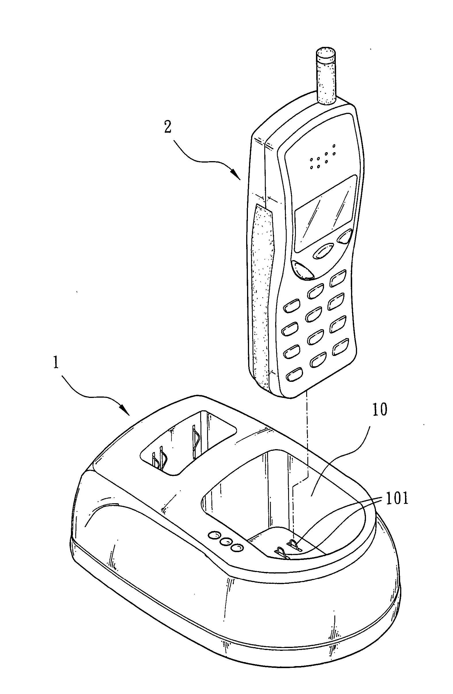
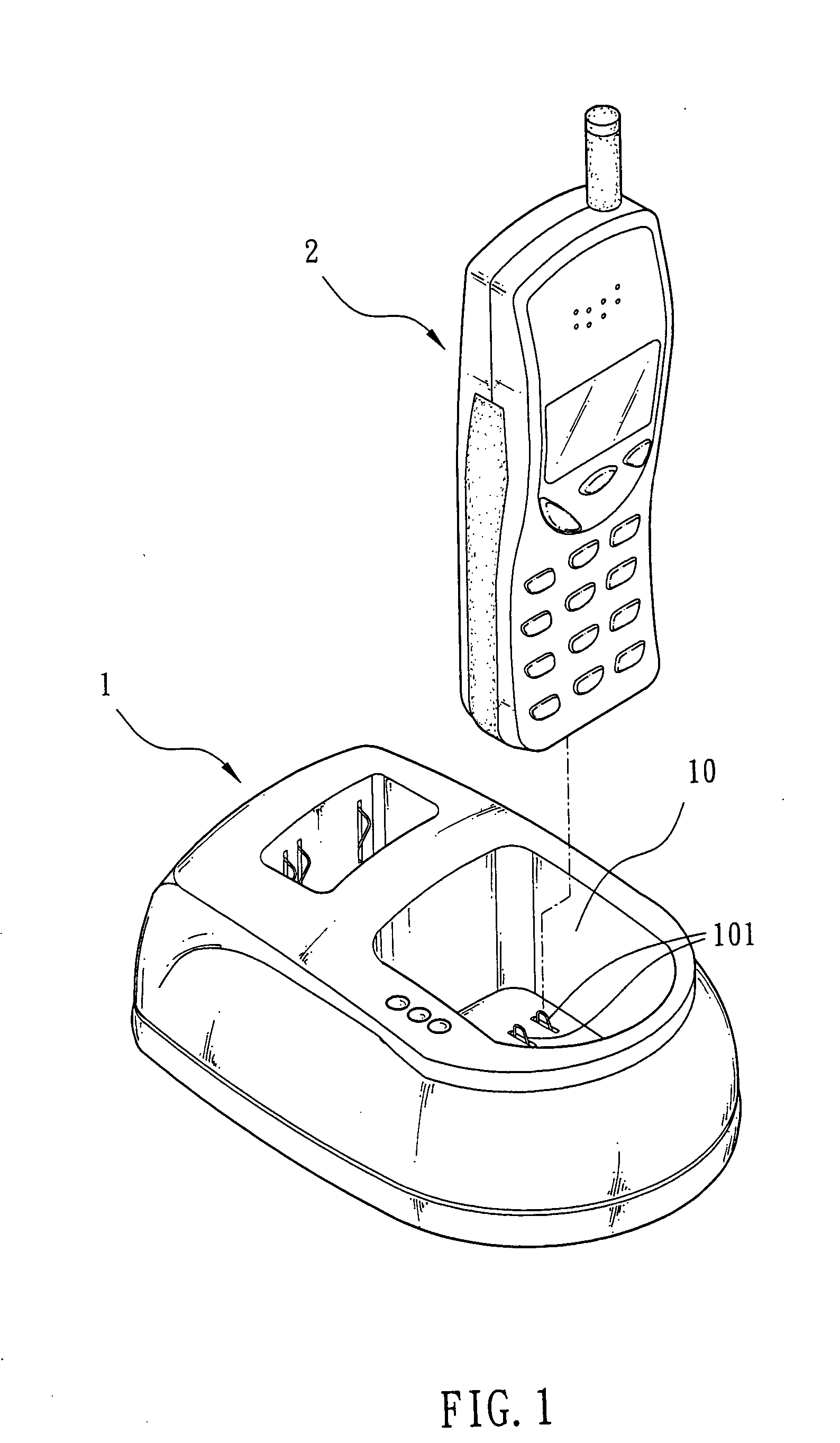
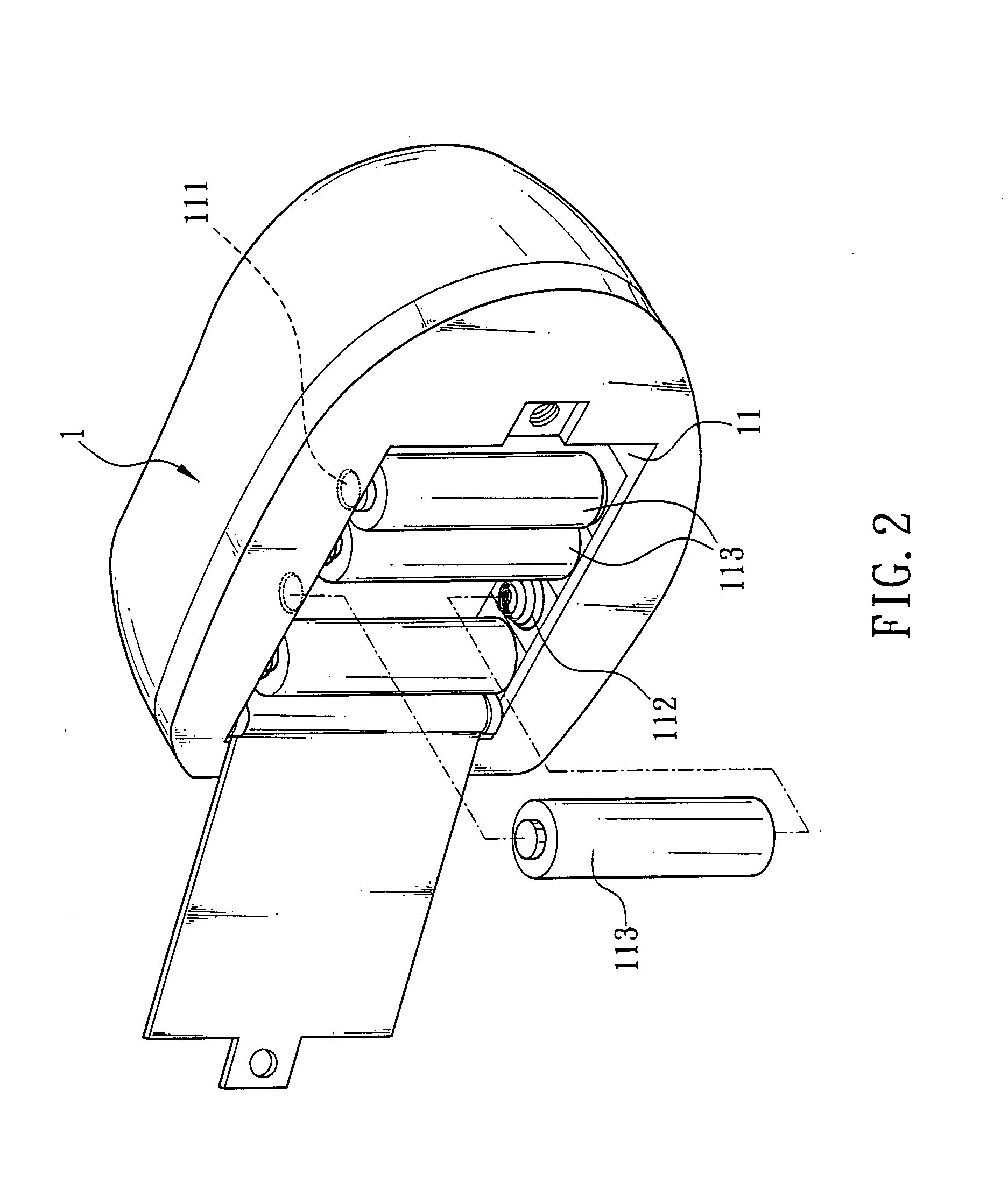
[0011] Referring to FIGS. 1, 2, and 3, a charger for cellular phone in accordance with the invention is shown. The charger comprises a body 1, a well 10 formed on one surface of the body 1, a pair of electrical contacts 101 in the well 10 (see FIG. 1), a battery compartment 11 on the opposite other surface of the body 1, and at least one pair (two pairs are shown) of positive and negative terminals 111, 112 in the battery compartment 11 with four cells (e.g., alkalic cells or batterys) 113 received in the battery compartment 11 to form an electrical connection. The charger further comprises a charging circuit 12 inside the body 1 (see FIG. 3). The charging circuit is electrically coupled to the electrical contacts 101, the pairs of the positive and negative terminals 111, 112, and a connector 13 having one end exposed on the body 1 respectively. Charging plugs 20 of a cellular phone 2 are electrically coupled to the electrical contacts 101 when the cellular phone 2 is rested on the ...


PUM


Abstract

The present invention is to provide a charger for cellular phone comprising a body having a well and a battery compartment on its opposite surfaces, at least one pair of positive and negative terminals in the battery compartment, at least one pair of electrical contacts on the well and a charging circuit inside the body being electrically coupled to and the electrical contacts and terminals respectively. When the cellular phone is rested on the well, charging plugs of the cellular phone are electrically coupled to the electrical contacts. Thus, the charging circuit is adapted to automatically supply power from either the external power source or the cells (or batterys) received in the battery compartment to charge at least one electrical energy storage element in the cellular phone.

Description


Claims


Application Information

Patent Timeline
Owner INVENTEC APPLIANCES CORP
Why Eureka
Try Eureka