Liquid supplying member, method of manufacturing the same, and liquid ejection apparatus incorporating the same

Active Publication Date: 2005-02-03
SEIKO EPSON CORP
View PDF10 Cites 16 Cited by
  • Summary
  • Abstract
  • Description
  • Claims
  • Application Information

AI Technical Summary

Benefits of technology

[0009] It is therefore an object of the present invention to provide a liquid supplying member in use for the liquid ejection apparatus in which a flexural rigidity of the ink supplying tube is reduced, and satisfactory anti-water permeability and gas barrier properties are realized at low cost, and to provide a liquid ejection apparatus provide with the liquid supplying tube
[0010] It is also an object of the invention to provide a liquid supplying member in which the liquid ejection apparatus body can be made compact and the attaching operation of the liquid supplying member can be facilitated.

Problems solved by technology

In any case, the result is a further size increase of the apparatus.
Where a multi-layer construction is introduced into the tube annular in cross section, it is basically unavoidable to increase the flexural rigidity.
This results in increase of cost to manufacture.

Method used


Image

  • Liquid supplying member, method of manufacturing the same, and liquid ejection apparatus incorporating the same
  • Liquid supplying member, method of manufacturing the same, and liquid ejection apparatus incorporating the same
  • Liquid supplying member, method of manufacturing the same, and liquid ejection apparatus incorporating the same

Examples


first embodiment

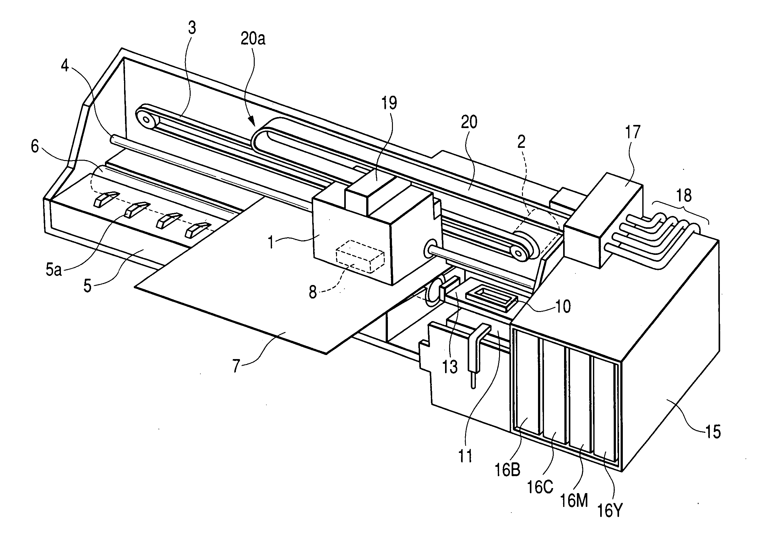
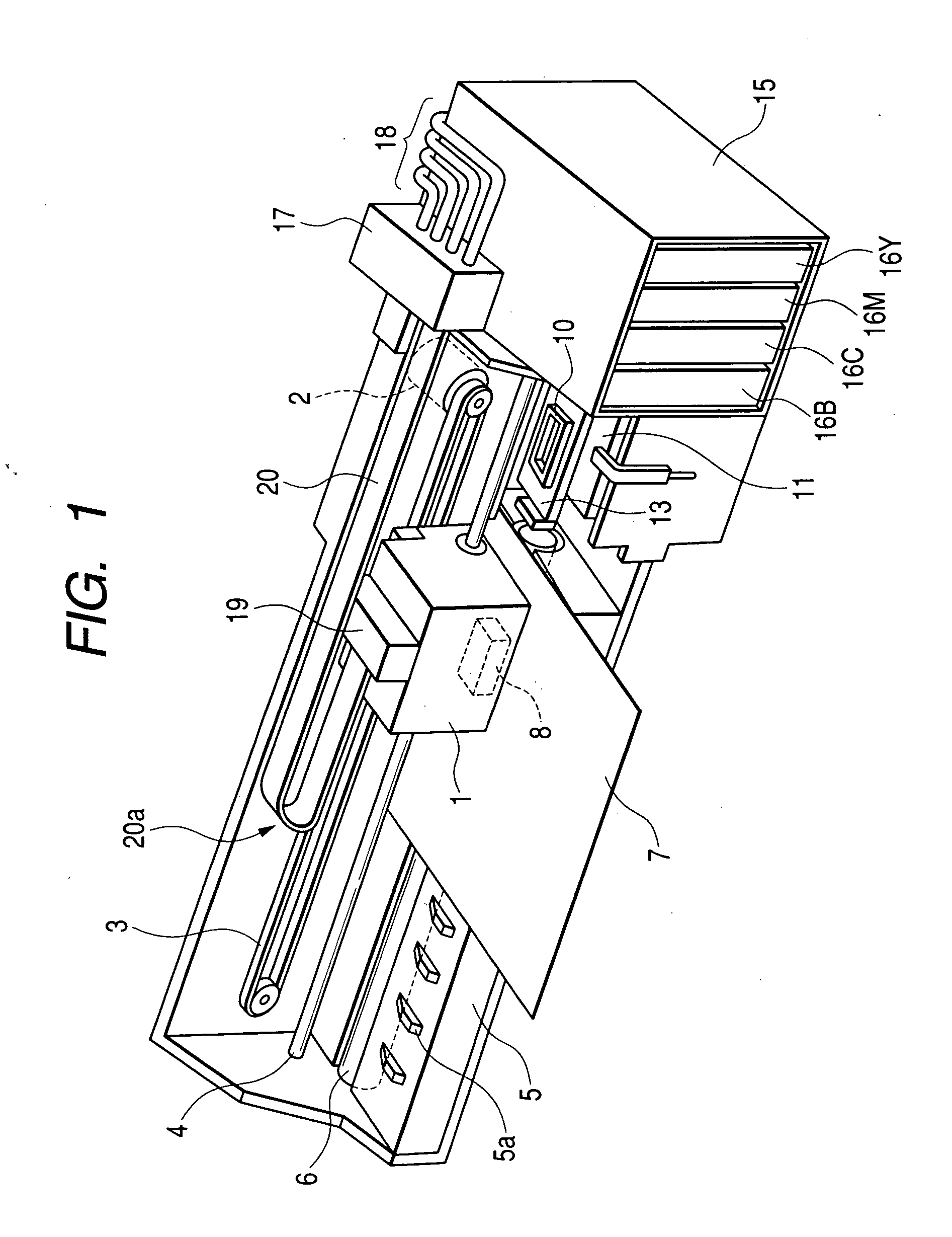
[0072]FIG. 1 shows an ink jet recording apparatus as an example of a liquid ejection apparatus incorporating a liquid supplying member according to the invention In the recording apparatus, a carriage 1 is reciprocatively moved in the primary scanning direction which extends along a longitudinal direction of a sheet feeder 5, while being guided by a guide member 4 with the aid of a timing belt 3 driven by a carriage motor 2

[0073] The sheet feeder 5 is provided with a sheet feeding roller 6. A recording sheet 7, nipped between the sheet feeding roller 6 and a follower roller (not shown), is transported by rotation of the sheet feeding roller 6 in a secondary scanning direction orthogonal to the primary scanning direction. A number of protrusions 5a are intermittently arrayed in the longitudinal direction on the upper face of the sheet feeder 5. The recording sheet 7 is transported along the top faces of the thus arrayed protrusions 5a.

[0074] An ink jet recording head 8, as indicated...

second embodiment

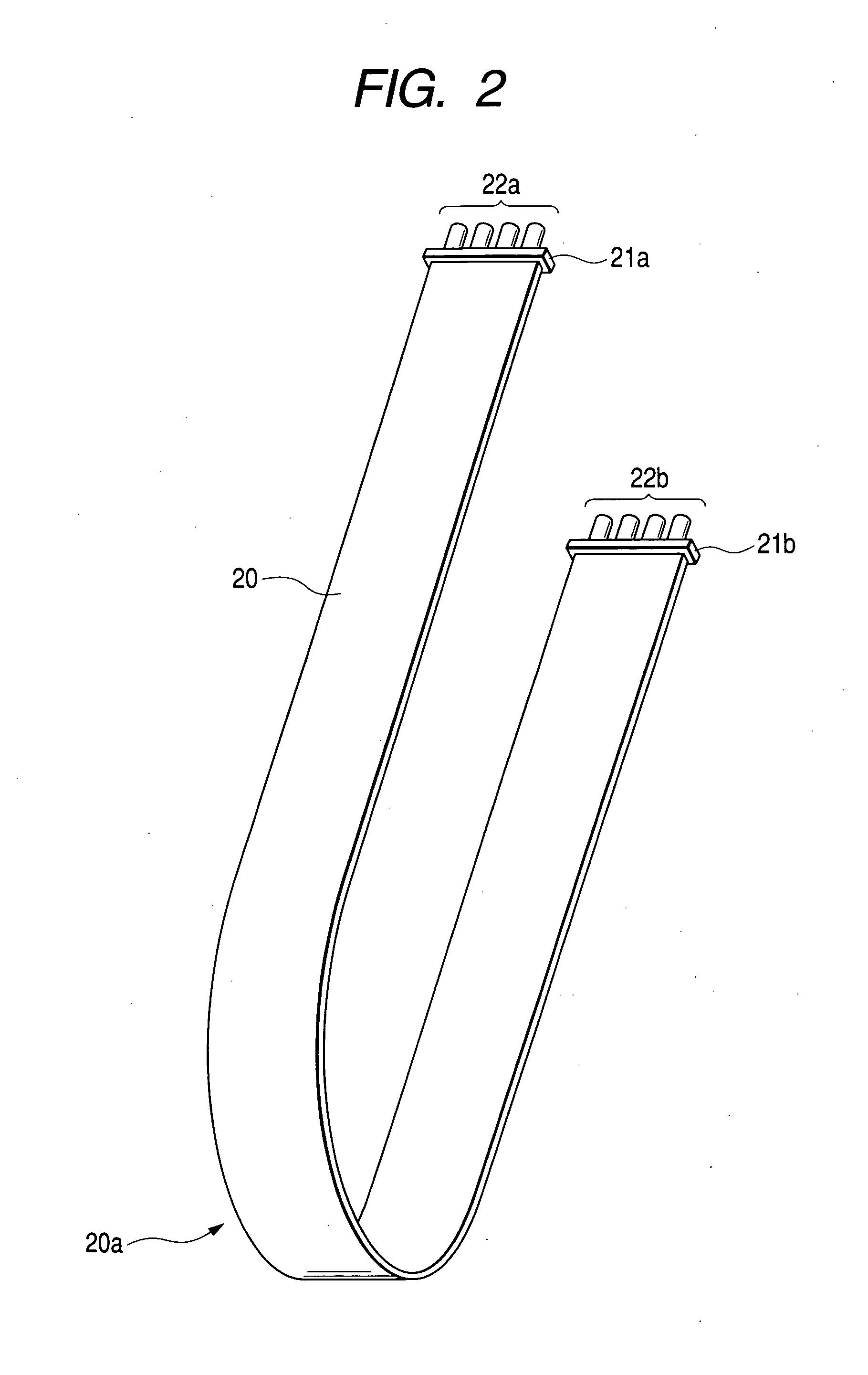
[0102] As in the second embodiment, since a single ink supplying passage 33 is provided in a single ink supplying tube 20, four independent tubes are to be incorporated in the apparatus shown in FIG. 1.

[0103] Although it is not explicitly shown in these figures, it is preferable to form thin films 34 on the outer faces of the film member 32 by aluminum lamination process, as in the case shown in FIG. 6.

fourth embodiment

[0104]FIGS. 11 and 12 show an ink jet recording apparatus 200 incorporating a liquid supplying member 100 according to the invention. The ink jet recording apparatus 200 further comprises: a carriage 142 performing a reciprocating motion over a recording medium not shown; a recording head (not shown) mounted on the carriage 142 so as to eject plural colors of ink onto the recording medium and thereby perform recording or the like; a plurality of cartridges 145 each storing one of the plural colors of ink. The carriage 142 is reciprocated along a guide shaft 148 by a motor not shown. The cartridges 145 are fixed on a main body of the ink jet recording apparatus 200. The liquid supplying member 100 is an elongated member and its main part is formed with a flexible material (such as a thermoplastic elastomer). The liquid supplying member 100 has a required number (a plural number, in this embodiment) of passages so as to supply plural colors of ink stored respectively in a plurality of...


PUM


Abstract

A liquid supplying member supplies liquid from a liquid container to a liquid ejection head which are provided in a liquid ejection apparatus. In the liquid supplying member, a flexible base member has a face formed with at least one groove. A flexible first plate member is joined to the face of the base member so as to seal at least a part of the at least one groove to form at least one liquid supplying passage, through which the liquid is supplied from the liquid container to the liquid ejection head. A first connector is monolithically formed with a longitudinal end portion of the base member to connect the at least one groove to one of the liquid container and the liquid ejection head.

Description

[0001] This is a continuation-in-part application of U.S. patent application No. 10 / 374,526 filed on Feb. 27, 2003, the disclosure of which is incorporated herein by reference.BACKGROUND OF THE INVENTION [0002] The invention relates to a liquid supplying member for supplying liquid contained in a liquid cartridge to a liquid ejection apparatus for effecting recording or printing operation. The invention also relates to a method of manufacturing such a liquid supplying member. [0003] For instance, the liquid ejection apparatus, such as an ink jet recording apparatus, subjects an object to recording or printing by ejecting liquid to the object while a liquid ejection head is reciprocally actuated. Liquid to be ejected to the object (e.g., ink) is supplied from a liquid container (e.g., a liquid cartridge) to a liquid ejection head (e.g., a recording head). [0004] In addition to the liquid ejection apparatus of the type having both a liquid ejection head and a liquid container mounted ...

Claims


Application Information

Patent Timeline
IPC IPC(8): B41J2/175B41J29/02
CPCB41J2/175B41J29/02B41J2/17509
Inventor SHIHO, AKIHIKOKIMURA, HITOTOSHIMATSUMOTO, HITOSHIKUMAGAI, TOSHIO
Owner SEIKO EPSON CORP
Why Eureka
Try Eureka