

Enclosure for a light source
a light source and enclosure technology, applied in the field of illumination, can solve the problem that the source is an obstacle to those moving near the wall
- Summary
- Abstract
- Description
- Claims
- Application Information
AI Technical Summary
Benefits of technology
Problems solved by technology
Method used
Image

Examples
Embodiment Construction
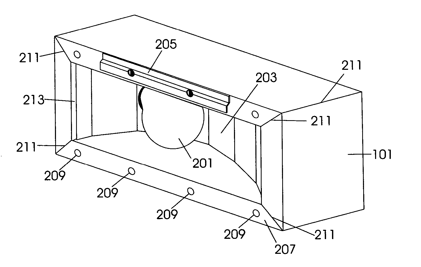
[0012] The following describes an apparatus including an enclosure in which a light source is disposed and which supports a part of the wall in which the apparatus is described. The enclosure may be disposed substantially within the wall, such that the enclosure does not provide an obstacle to those moving near the wall. Because the enclosure is capable of supporting a part of the wall, the enclosure may be substituted for one or more substructures of the wall, including, but not limited to, concrete blocks, cement blocks, bricks, cinder blocks, and combinations thereof. Because of its supporting nature, the enclosure may be disposed at most any height in the wall, and thus provides more direct light to the desired area.
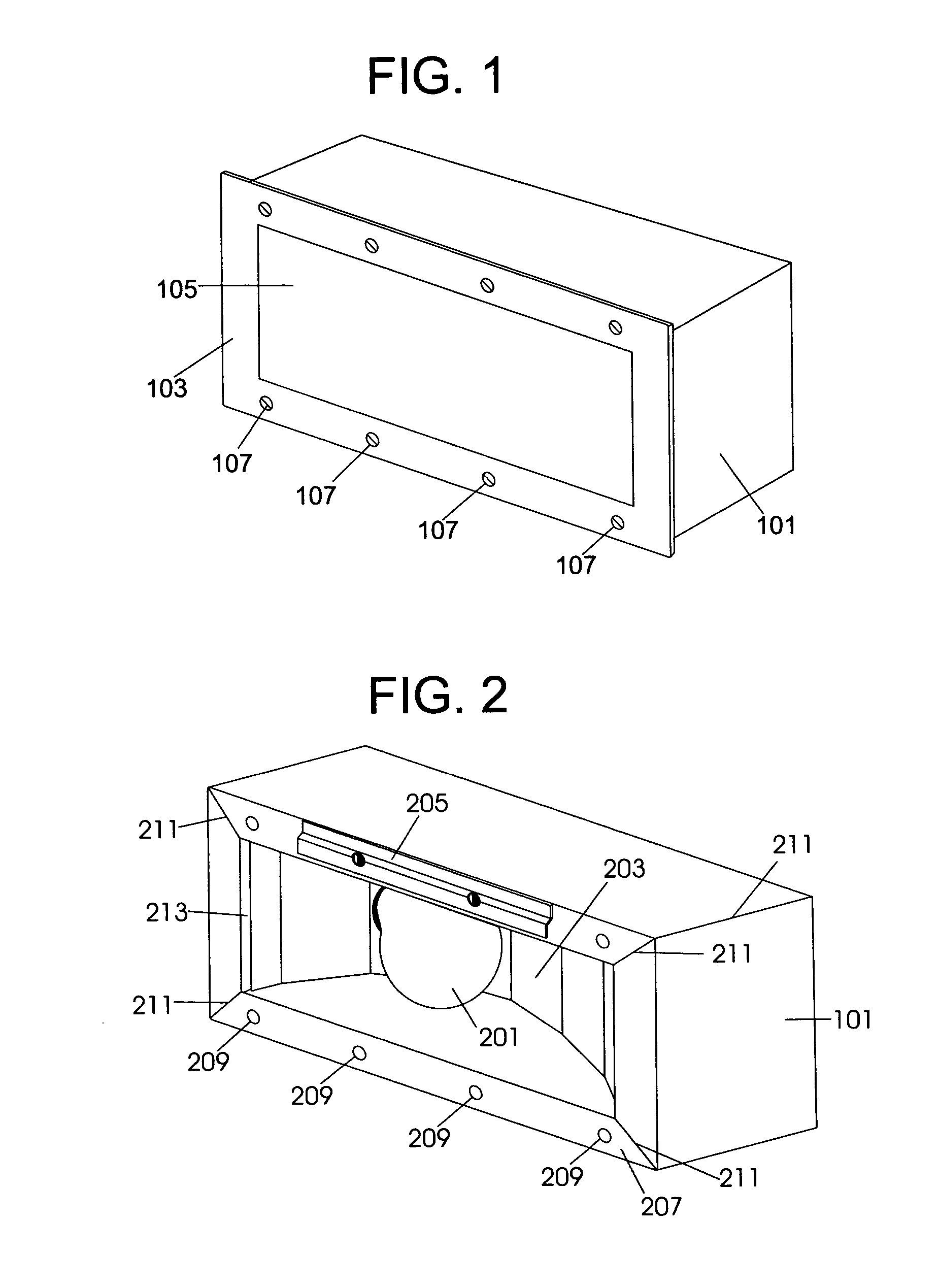
[0013] A perspective view of an enclosure 101 for a light source with a cover plate 103 is shown in FIG. 1. The enclosure 101 is typically shaped to mate with an opening in a wall. The enclosure is designed such that it is capable of supporting a part of the wall. A...
PUM
 Abstract
Description
Claims
Application Information