
Light module for a headlamp of a vehicle with at least one adjustment unit

a technology of adjustment unit and light module, which is applied in the direction of fixed installation, lighting and heating apparatus, transportation and packaging, etc., can solve the problems of large installation space, complex actuator and gear tuning, and large amount of motor gear units, etc., and achieves small loss of efficiency, good value, and large reduction

Inactive Publication Date: 2017-08-17
HELLA KG HUECK & CO
View PDF1 Cites 0 Cited by
  • Summary
  • Abstract
  • Description
  • Claims
  • Application Information

AI Technical Summary

Benefits of technology

The invention is a light module and adjustment unit for a headlamp that uses eccentric gear. The disc-shaped basic structure of the eccentric gear extends around the output axle and the adjusting axis, resulting in a compact design. The output axle is directly coupled with the light unit, minimizing loss of efficiency and ensuring angular accuracy. The adjustment unit can be executed in a space-saving design and can achieve highly dynamic light functions with minimal vibration and noise. The gear design results in minimal installation space requirement. These technical effects translate into high torque and longevity, making the adjustment unit ideal for headlamp applications.

Problems solved by technology

Often, the mass and torques requirements in combination with the angle resolution requirements are so high, that complicated actuator and gear tuning is required.
Particularly due to the need for at least two adjustment units, the motor-gear-units are often very complex and they take up a large amount of installation space, which is often not available in a headlamp housing.
This causes major installation space requirements and due to the many coupling elements contained in the moving system, the angular accuracy cannot fulfill high demands.
These solutions require extensive installation space and lead to larger weights which in turn lead to additional energy consumption in the vehicle.
When a small motor with standard gears is used, this leads to an increase in the number of component parts and therefore to an increase in system complexity.

Method used


Image

  • Light module for a headlamp of a vehicle with at least one adjustment unit
  • Light module for a headlamp of a vehicle with at least one adjustment unit
  • Light module for a headlamp of a vehicle with at least one adjustment unit

Examples


Embodiment Construction

[0023]Further measures improving the invention are described below in combination with a preferred embodiment of the invention by means of the figures. The figures show:

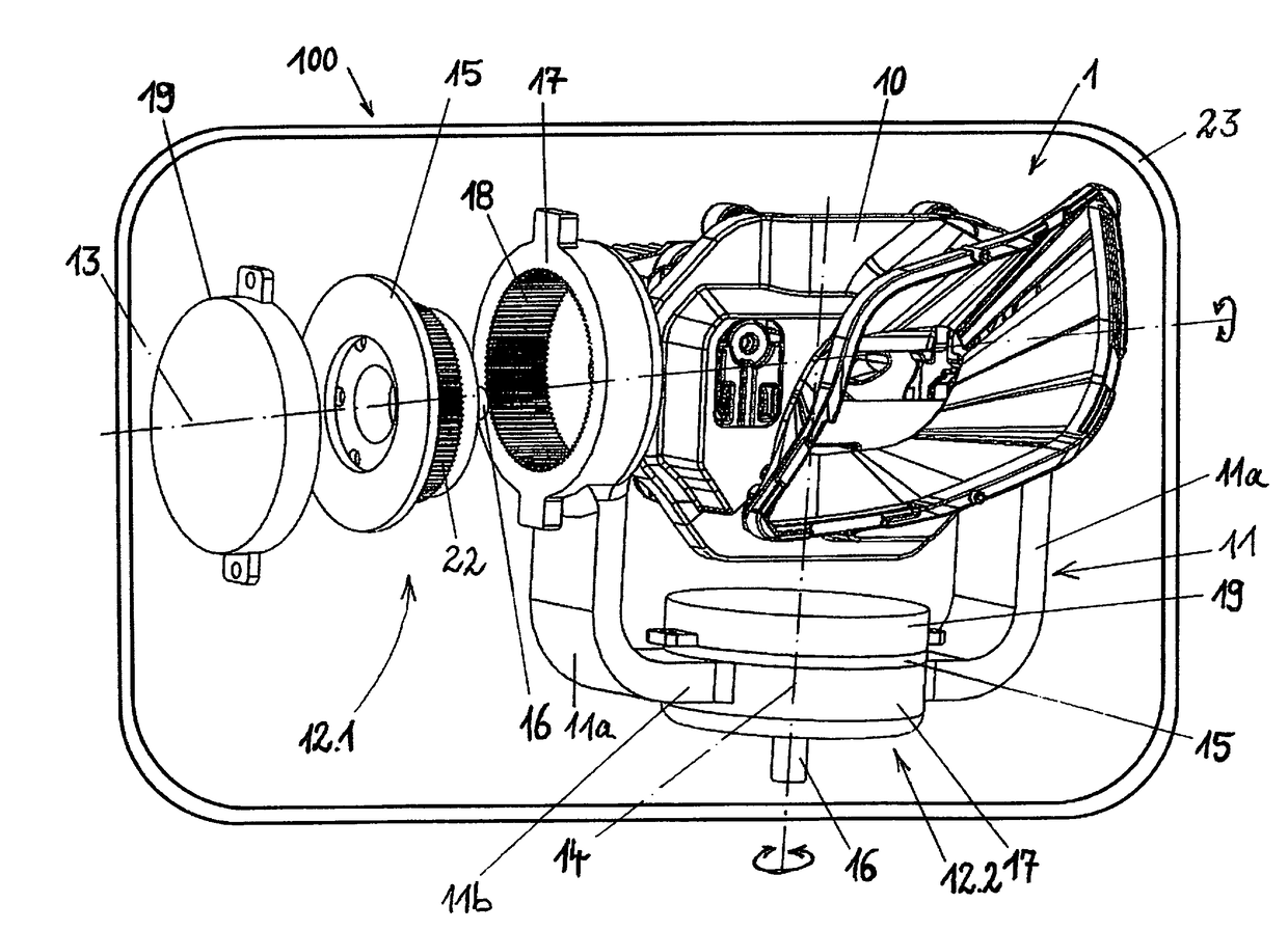
[0024]FIG. 1 A perspective view of a light module with adjustment units for the movement of a light unit of a light module, wherein an adjustment unit is shown in an exploded view.

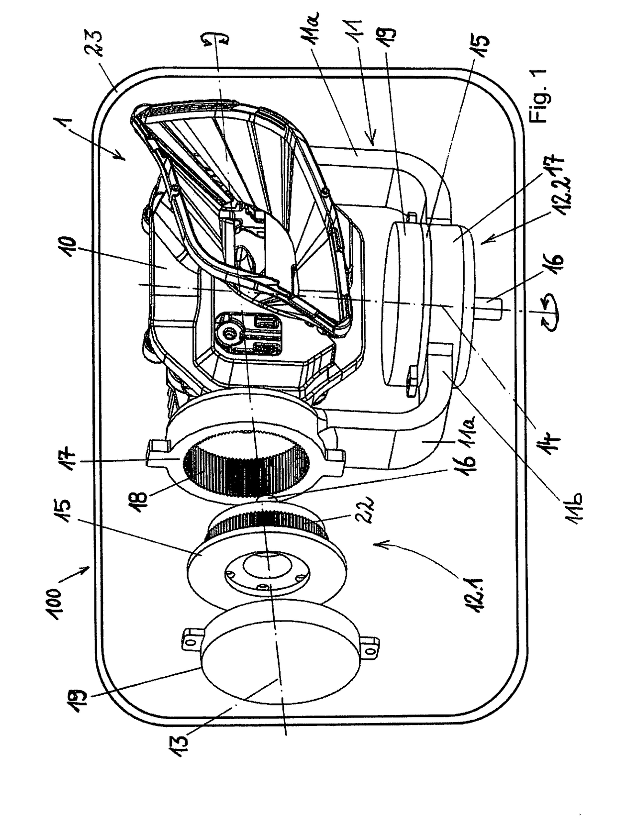
[0025]FIG. 2 A perspective view of the light module according to FIG. 1 in the assembled state.

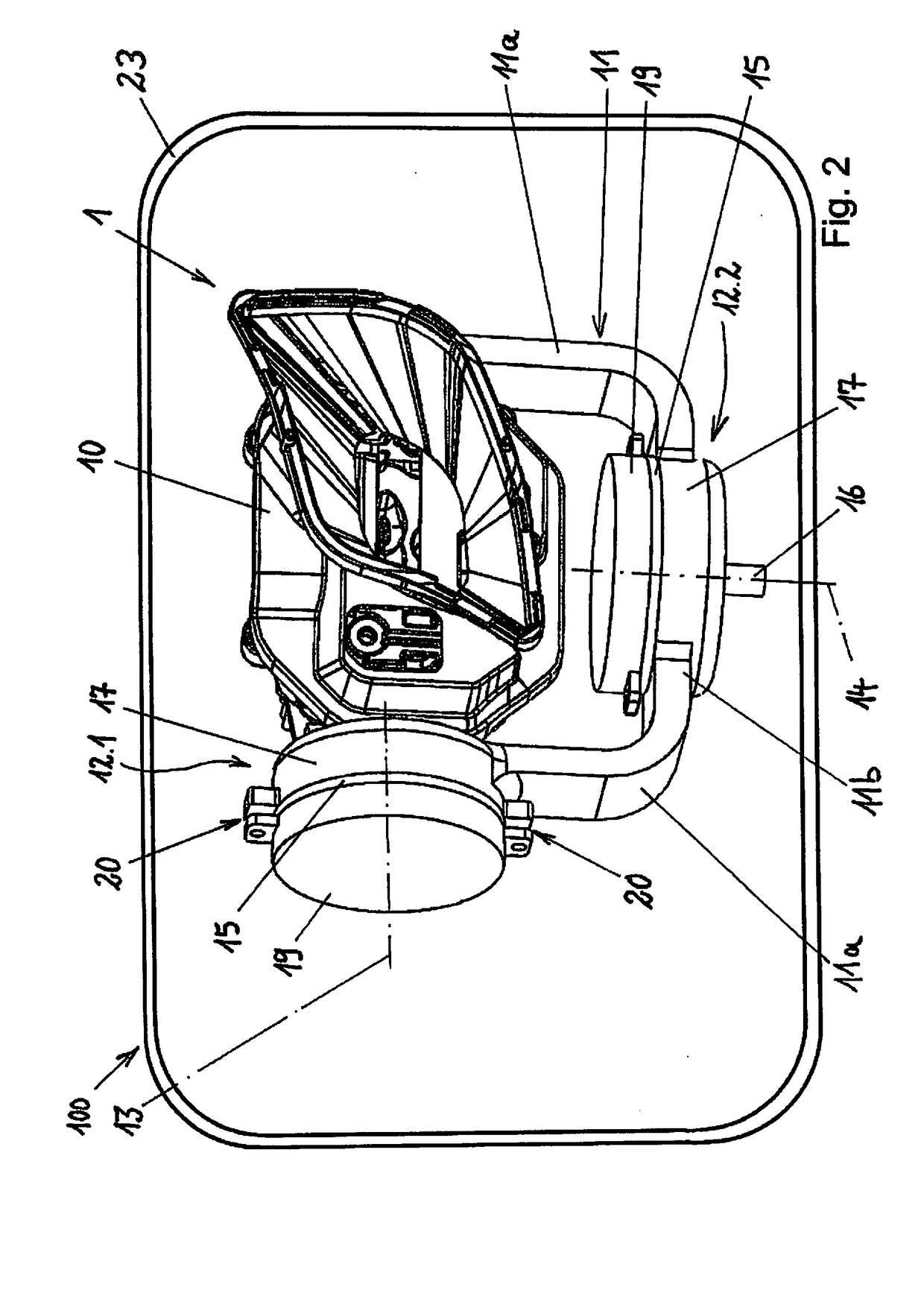
[0026]FIG. 3 A perspective view of the motor and the eccentric gear used to form an adjustment unit.

[0027]FIGS. 1 and 2 show a perspective view of a light module 1 being received in a headlamp 100, wherein the headlamp 100 is represented only in a schematic manner by a headlamp housing 23. The light module 1 has a light unit 10, and the light unit 10 is movably held in the headlamp housing 23 of the headlamp 100 via a carrier frame 11 of the light module 1. The light unit 10 serves the emission of light, for example for the forming of a low beam a...


PUM


Abstract

A light module for reception in a headlamp of a vehicle. The light module includes at least one light unit for the emission of light, and a carrier frame in which the light unit is held in the headlamp. At least one adjustment unit is also provided, by means of which the light unit can be moved in the headlamp around at least one adjusting axis. The adjustment unit has an eccentric gear with an output axle coinciding with the adjusting axis. A basic structure of the eccentric gear extends around the output axle in a disc-shaped manner.

Description

[0001]The present invention relates to a light module for reception in a headlamp of a vehicle, at least comprising one light unit for the emission of light and comprising a carrier frame in which the light unit is held in the headlamp and wherein at least one adjustment unit is provided, by means of which the light unit can be moved in the headlamp around at least one adjusting axis.STATE OF THE ART[0002]Known headlamps for vehicles have light modules which are movably held in the headlamp housing, and the movement of the light module in the headlamp housing is often executed in a highly dynamic manner. With regard to the swiveling of the light module in the headlamp for the generation / dynamization of, for example, bend lighting, a dazzle-free high beam or a marker light, actuators and gears are driven, which need to comply with the respective specific requirements. In addition to a long service life, the requirements include high torque, high movement speed, high angular accuracy,...

Claims


Application Information

Patent Timeline
IPC IPC(8): F21S8/10
CPCF21S48/1742B60Q1/076F21S41/657
Inventor PAI, ARATHISCHAFER, SOREN
Owner HELLA KG HUECK & CO
Learn More