When a vehicle component begins to fail, the repair cost is frequently minimal if the impending failure of the component is caught early, but increases as the repair is delayed.
Sometimes, if a component in need of repair is not caught in a timely manner, the component, and particularly the impending failure thereof, can cause other components of the vehicle to deteriorate.
One example is where the water pump fails gradually until the vehicle overheats and blows a
head gasket.
Another example is when a tire gradually loses air until it heats up, fails and causes an accident.
In these cases, the warning often comes too late as most vehicle gages alert the driver after he or she can conveniently solve the problem.
Other drivers can sense that their vehicle is performing differently but they don't know why or when a component will fail or how serious that failure will be, or possibly even what specific component is the cause of the difference in performance.
There are no systems currently on automobiles to monitor the numerous vehicle components over time and to compare component performance with normal performance.
Additionally, there is no
system currently existing on a vehicle to look for erratic behavior of a vehicle component and to warn the driver or the dealer that a component is misbehaving and is therefore likely to fail in the very near future.
Sometimes, when a component fails, a catastrophic accident results.
Similarly, other component failures can lead to loss of control of the vehicle and a subsequent accident.
The
system of this patent does not predict or warn the operator or the home base of a pending problem.
This system only reports failures after they have occurred and does not predict them.
In this case, the
signal from the manifold absolute
pressure sensor may be indicative of a fault in the intake of air into the engine, e.g., the engine is drawing in too much or too little air, and is thus affected by the operation of the engine.
However, the system of Marko et al. does not detect faults in the sensors that are conducting the measurements, e.g., a fault in the
exhaust gas oxygen sensor, or faults that are only developing but have not yet manifested themselves or faults in other systems.
Every automobile driver fears that his or her vehicle will break down at some unfortunate time, e.g., when he or she is traveling at night, during
rush hour, or on a long trip away from home.
However, vehicles perform such monitoring typically only for the vehicle driver and without communication of any impending results, problems and / or vehicle malfunction to a remote site for trouble-shooting, diagnosis or tracking for
data mining.
In the past, systems that provide for remote monitoring did not provide for automated analysis and communication of problems or potential problems and recommendations to the driver.
As a result, the vehicle driver or user is often left stranded, or irreparable damage occurs to the vehicle as a result of
neglect or driving the vehicle without the user knowing the vehicle is malfunctioning until it is too late, such as low oil level and a malfunctioning warning light, fan belt about to fail, failing radiator hose etc.
Also, Scholl et al. does not teach the diagnostics of the problem or potential problem on the vehicle itself nor does it teach the automatic diagnostics or any
prognostics.
Of course there are many areas of the country where
cell phone reception is not available and thus a system that relies on the availability of such a system for diagnostics will not always be available and thus has a significant failure mode.
Furthermore, it would be difficult if not impossible for such a location to have all of the information to diagnose problems with all vehicle models that are on the road and to be able to retrieve that information and act on
raw data on a continuous basis to keep track of whether all vehicles on the roadways are operating properly and to forecast all potential problems with each vehicle.
Additionally is a
human operator is required then the system quickly becomes unmanageable.
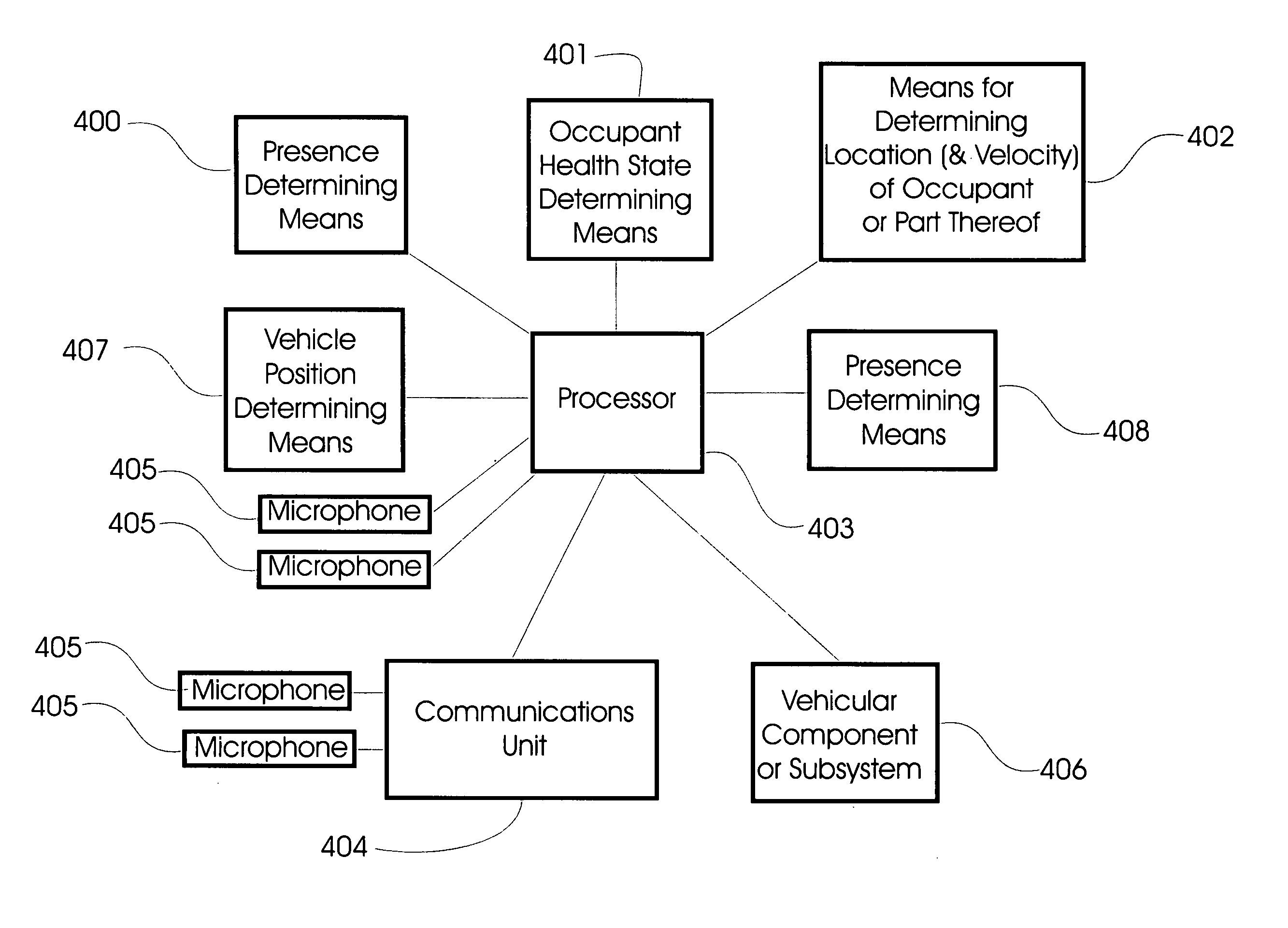
Thus, the state of the vehicle could be normal when the vehicle is operating properly on a highway or abnormal when, for example, the vehicle is experiencing excessive angular inclination (e.g., two wheels are off the ground and the vehicle is about to
rollover), the vehicle is experiencing a
crash, the vehicle is skidding, and other similar situations.

