Shelf with lighting function for a domestic cooling device

a technology for domestic cooling and shelves, applied in domestic cooling devices, semiconductor devices for light sources, lighting and heating devices, etc., can solve the problem of light reflection surface risk, if any, and achieve the effect of high illumination power

Active Publication Date: 2020-07-28
EMZ HANAUER
View PDF11 Cites 1 Cited by
  • Summary
  • Abstract
  • Description
  • Claims
  • Application Information

AI Technical Summary

Benefits of technology

[0005]It is an object of the invention to provide a shelf with a lighting function for use in a domestic cooling device, which, while having a high illuminating power, allows a target region to be illuminated as uniformly as possible.
[0012]A lens element having a collecting function can be arranged in the propagation path of the light of the light source element in front of the light reflection surface. The lens element can in particular effect at least approximate collimation of a light beam emitted by the light source element. The provision of the lens element allows the light reflection surface to be formed with a comparatively small surface area, the scattering properties of the light reflection surface nevertheless allowing a comparatively large target region to be illuminated.
[0014]In some embodiments, the light reflection surface, when viewed in a section perpendicular to the strip longitudinal direction, is curved in an arcuate manner. In this sectional view, it extends from a region within the height of the base plate to a point at a distance from and beneath the base plate, and at the same time is arranged laterally outside the base plate but facing towards the base plate. This makes it possible to arrange the light reflection surface in such a manner that it is concealed from view to an observer looking at the edge strip head on, and at the same time to direct all the light provided by the light source element into the region beneath the base plate.

Problems solved by technology

There is only a slight, if any, risk of absorption losses at the light reflection surface.

Method used


Image

  • Shelf with lighting function for a domestic cooling device
  • Shelf with lighting function for a domestic cooling device
  • Shelf with lighting function for a domestic cooling device

Examples


Embodiment Construction

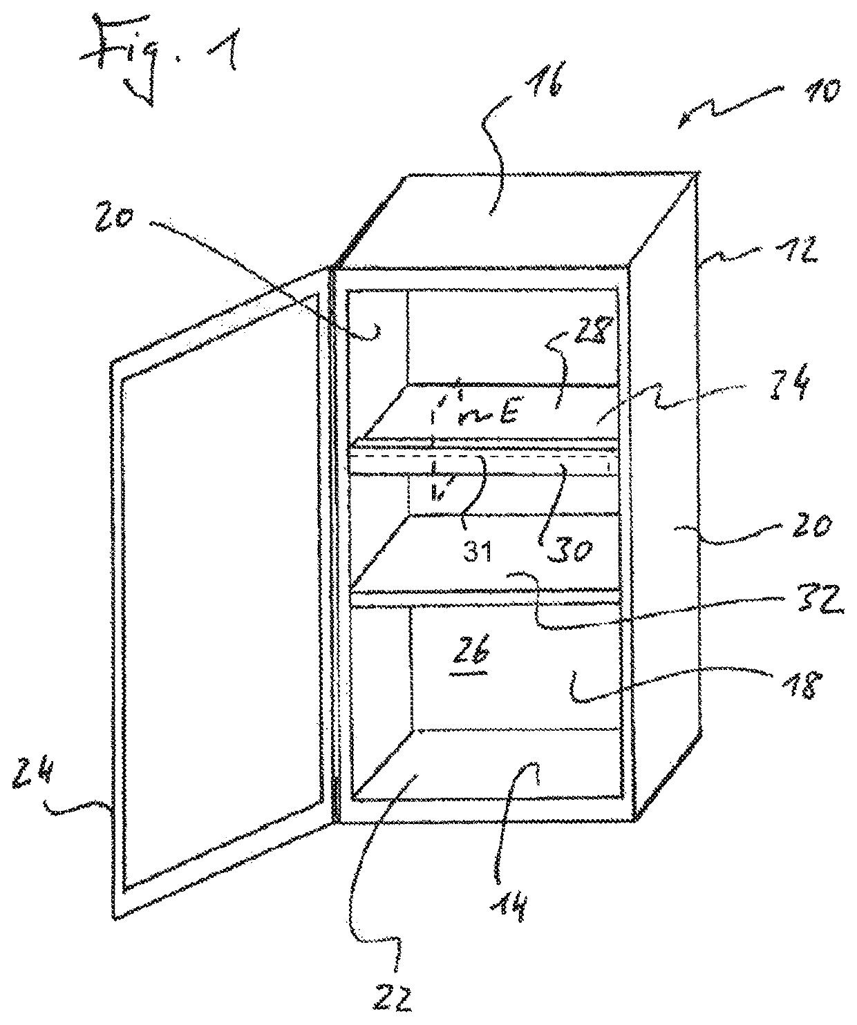
[0020]Reference will first be made to FIG. 1. The device shown therein is designated generally 10. It is a cooling device of the cabinet type, which serves to store foods cold and, if required, can additionally have a freezer compartment which either is arranged inside the cooling chamber of the refrigerator 10 and can be closed relative to the cooling chamber by a flap or—as in the case of top-freezer or bottom-freezer refrigerators—is situated above or below the cooling chamber. It should be added that the expression cooling device within the context of the present disclosure is to be interpreted broadly and is also to include devices which serve solely to store foods in the frozen state (i.e. freezer).

[0021]The refrigerator 10 has a cabinet body 12 having a bottom wall 14, a top wall 16, a rear wall 18 and two side walls 20. The cabinet body 12 forms an access opening 22 bordered by the bottom wall 14, the top wall 16 and the two side walls 20, which access opening can be closed ...


PUM


Abstract

A shelf for a domestic cooling device has a base plate with an edge face, an edge strip extending along the edge face of the base plate where the edge strip has a strip body covering the edge face, and at least one light source element where the strip body forms a light reflection surface which is arranged in a propagation path of the light of the at least one light source element and has a diffuse reflecting effect for at least a portion of the light that is incident thereon.

Description

BACKGROUND OF THE INVENTION1. Field of the Invention[0001]The present invention relates generally to a shelf for a domestic cooling device, where the shelf has a lighting function for illuminating an interior of the cooling device serving as a cooling chamber or at least parts of the cooling chamber. The present invention relates further to a domestic cooling device equipped with such a shelf.2. Description of the Prior Art[0002]Cooling devices for domestic use usually have built-in lighting means which, when the cooling device is open, light the interior in order to give the user a better view of the foods in the cooling chamber. One possibility for illuminating the cooling chamber which has become known in the prior art consists in fitting a strip-like elongate lighting module to a shelf which can be removed from the cooling chamber if required and on which foods can be placed. The lighting module is thereby mounted in the region of an edge face of a base plate of the shelf and ex...

Claims


Application Information

Patent Timeline
Patent Type & Authority Patents(United States)
IPC IPC(8): F25D27/00F25D25/02F21V7/00F21Y115/10
CPCF21V7/0008F25D25/02F25D27/00F21Y2115/10F25D11/00F21V5/04F21V23/003F21V7/00
Inventor SIGNORINO, MANFREDIBRABEC, MARTINSCHENKL, JOHANN
Owner EMZ HANAUER
Why Eureka
Try Eureka