
Aspiration catheter having a variable over-the-wire length and methods of use

a catheter and variable technology, applied in the field of catheters, can solve the problems that the distal tube cannot be completely extracted from the proximal tube lumen, and the distal tube lumen cannot be completely extracted from the distal tube lumen, so as to shorten the effective over-the-wire length of the catheter

Inactive Publication Date: 2005-02-03
MEDTRONIC AVE
View PDF16 Cites 136 Cited by
  • Summary
  • Abstract
  • Description
  • Claims
  • Application Information

AI Technical Summary

Benefits of technology

[0014] Accordingly, disclosed herein is an aspiration catheter with an aspiration shaft and a telescoping outer sheath. The sheath includes “nesting” proximal and distal tubes. Each tube has a single lumen and is slidably disposed over the aspiration shaft. The distal tube is sized to slide proximally and distally within the proximal tube lumen, and the aspiration shaft is sized to slide proximally and distally within a distal tube lumen. Further, the distal tube cannot be completely extracted from the proximal tube lumen, and the aspiration shaft cannot be completely extracted from the distal tube lumen. As such, the catheter can be placed in an expanded position either by pulling the distal end of the aspiration shaft or by pushing the aspiration shaft, thereby causing the distal tube to be moved distally. The catheter can be retracted to a rapid-exchange length by pulling the aspiration shaft proximally so that the distal tube is drawn into the proximal tube lumen, thereby shortening the effective over-the-wire length of the catheter.

Problems solved by technology

Further, the distal tube cannot be completely extracted from the proximal tube lumen, and the aspiration shaft cannot be completely extracted from the distal tube lumen.

Method used


Image

  • Aspiration catheter having a variable over-the-wire length and methods of use
  • Aspiration catheter having a variable over-the-wire length and methods of use
  • Aspiration catheter having a variable over-the-wire length and methods of use

Examples


Embodiment Construction

[0023] Specific embodiments of the present invention are now described with reference to the figures, where like reference numbers indicate identical or functionally similar elements.

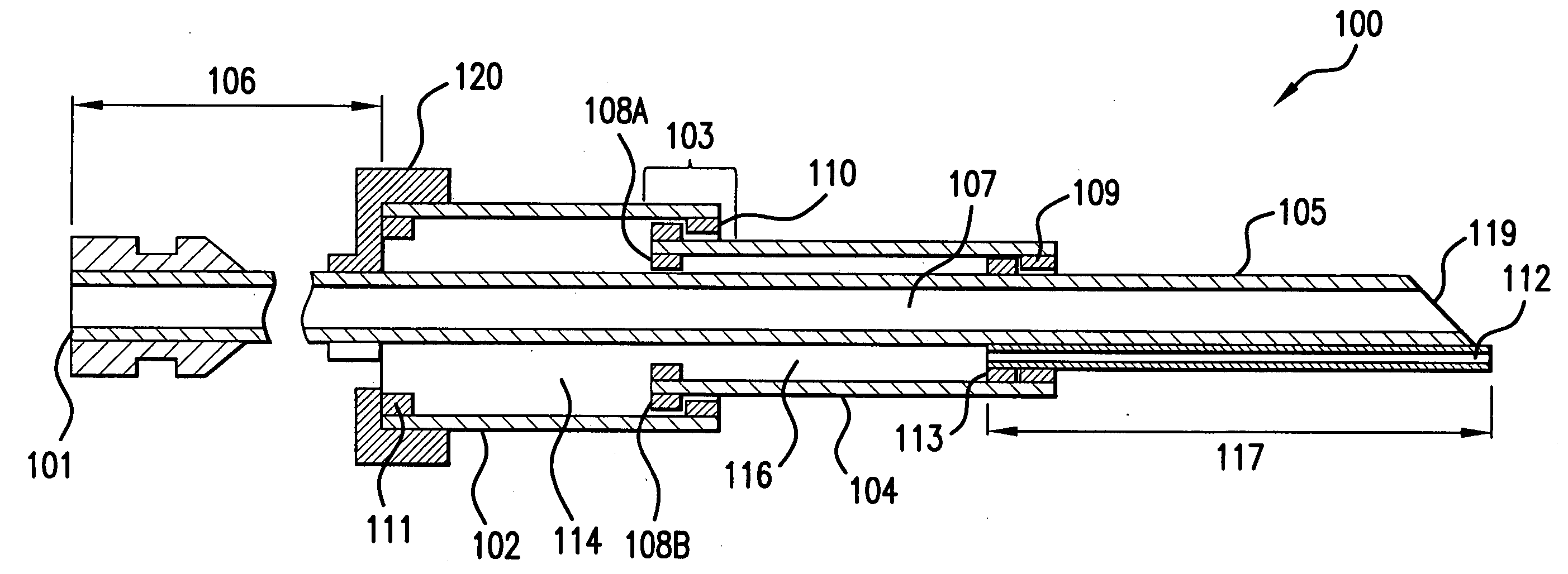
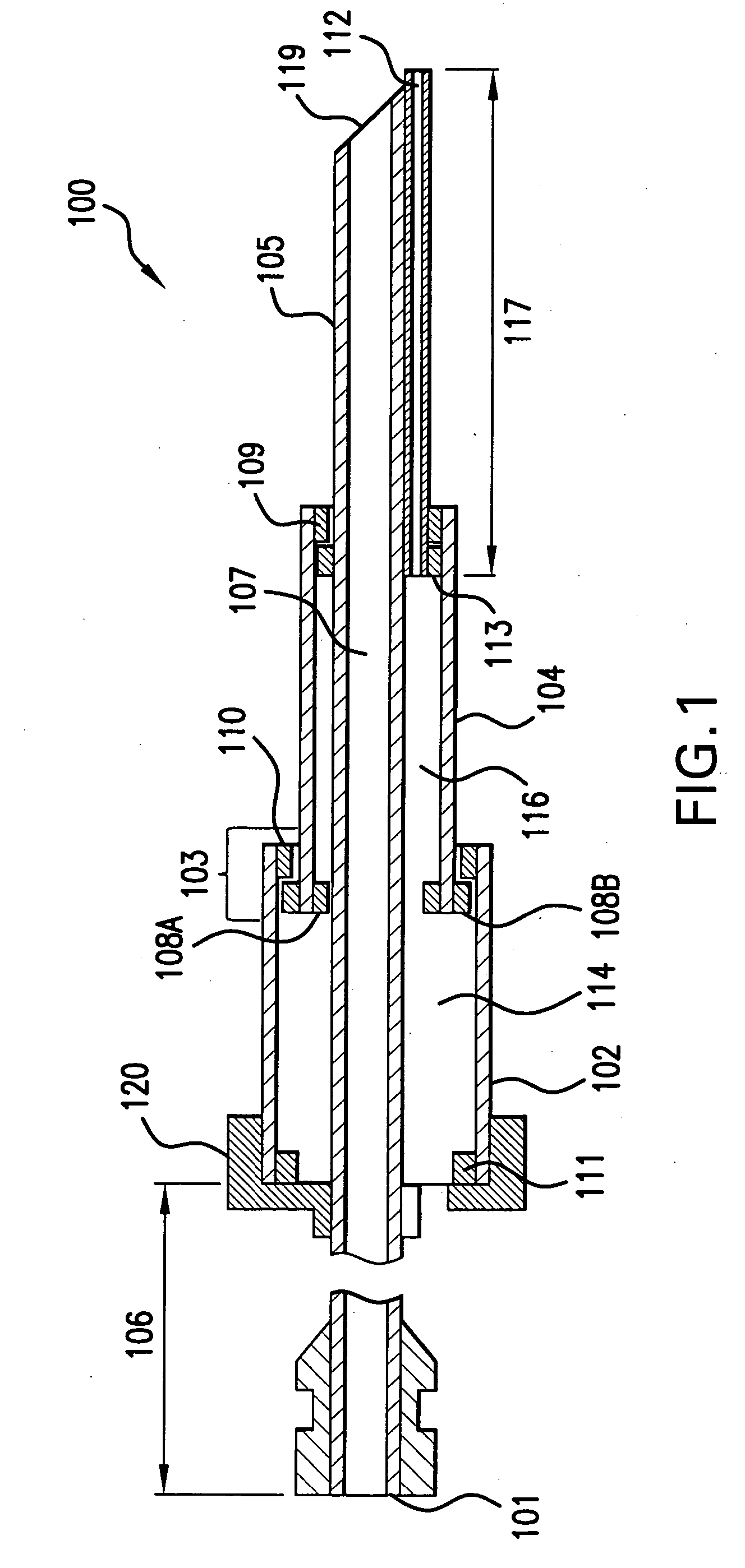
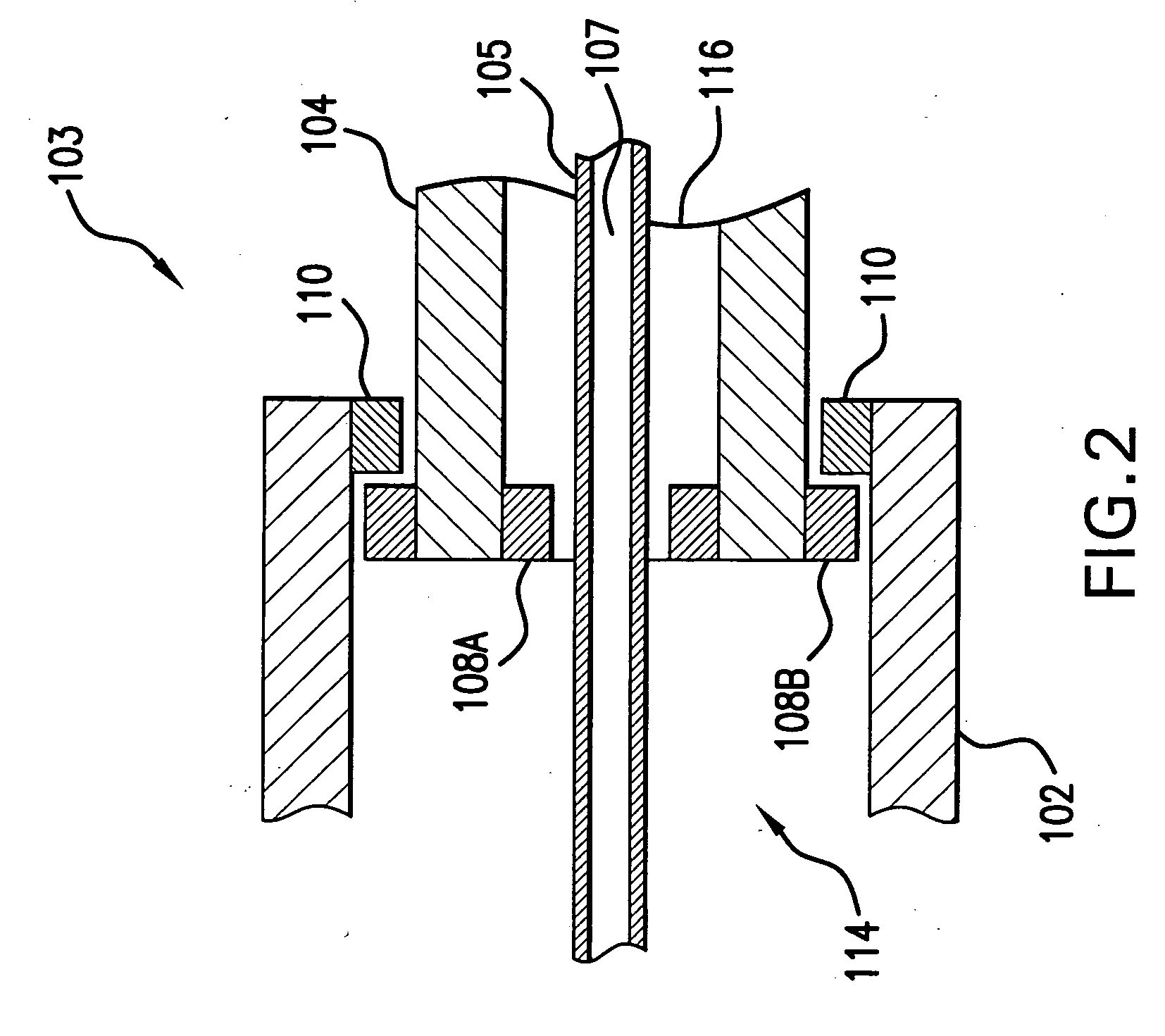
[0024] Referring now to FIG. 1, an aspiration catheter 100 is shown. Aspiration catheter 100 includes a proximal aspiration port 101, an aspiration shaft 105, a proximal tubular element 102, and a distal tubular element 104. Proximal tubular element 102 is open at both ends with a lumen 114 extending therethrough. Distal tubular element 104 is also open at both ends with a lumen 116 extending therethrough.

[0025] Aspiration shaft 105 having an aspiration lumen 107 is similar to other tubular members known in the art that are suitable for aspirating embolic or thrombotic matter from a vessel. Aspiration shaft 105 is a long, continuous tubular body having a proximal segment 106 that extends proximal of proximal tubular element 102 and a distal segment 117 that extends distal of distal tubular element 104...


PUM


Abstract

An aspiration catheter includes an aspiration shaft and a telescoping outer sheath which can be passed over a guidewire. The sheath includes “nesting” proximal and distal tubes. The distal tube slides within a proximal tube lumen, and the aspiration shaft slides within a distal tube lumen. The catheter can be placed in an expanded position by pushing the aspiration shaft, thereby causing the distal tube to be moved distally. The catheter can be retracted by pulling the aspiration shaft proximally so that a distal segment of the aspiration shaft is drawn into the distal tube lumen and the distal tube is drawn into the proximal tube lumen. Alternatively, a middle tube is slidingly disposed over the aspiration shaft between the proximal and distal tubes. In this embodiment, the middle tube nests within the proximal tube lumen and the distal tube nests within a middle tube lumen.

Description

BACKGROUND OF THE INVENTION [0001] 1. Field of the Invention [0002] This invention relates to catheters for use within a body of a patient, and more particularly to aspiration catheters for removing debris from a body lumen. [0003] 2. Background of the Invention [0004] Catheters have long been used for the treatment of diseases of the cardiovascular system, such as treatment or removal of stenosis. For example, in a percutaneous transluminal coronary angioplasty (PTCA) procedure, a catheter is used to insert a balloon into a patient's cardiovascular system, position the balloon at a desired treatment location, inflate the balloon, and remove the balloon from the patient. Another example is the placement of a prosthetic stent that is placed in the body on a permanent or semi-permanent basis to support weakened or diseased vascular walls to avoid catastrophic rupture thereof. [0005] Often, more than one interventional catheter is used during a procedure, such as to change the size of ...

Claims


Application Information

Patent Timeline
IPC IPC(8): A61M1/00
CPCA61M1/008A61M2025/1068A61M2025/0175A61M2025/0004A61M1/84
Inventor DOUK, NAREAK
Owner MEDTRONIC AVE
Learn More