
Connector pin assembly and associated apparatus

a technology of connecting pins and connectors, applied in the direction of mechanical devices, constructions, fastening means, etc., can solve the problems of high cost, complex construction and use, and safety hazards of personnel installation and removal,

Active Publication Date: 2005-02-10
HENSLEY INDUSTRIES INC
View PDF35 Cites 36 Cited by
  • Summary
  • Abstract
  • Description
  • Claims
  • Application Information

AI Technical Summary

Problems solved by technology

This conventional need to pound in and later pound out the connector structure can easily give rise to a safety hazard for the installing and removing personnel.
While these alternative connector structures desirably eliminate the need to pound a connector structure into and out of an adapter nose they typically present various other types of problems, limitations and disadvantages including, but not limited to, complexity of construction and use, undesirably high cost, difficult installation and removal and unintentional operational dislodgment of the installed connector structure from its associated tooth point and support structure.

Method used


Image

  • Connector pin assembly and associated apparatus
  • Connector pin assembly and associated apparatus
  • Connector pin assembly and associated apparatus

Examples


Embodiment Construction

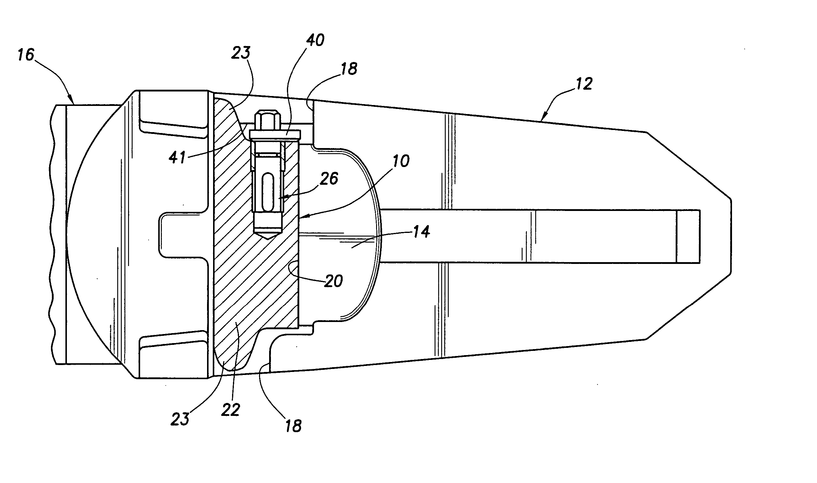
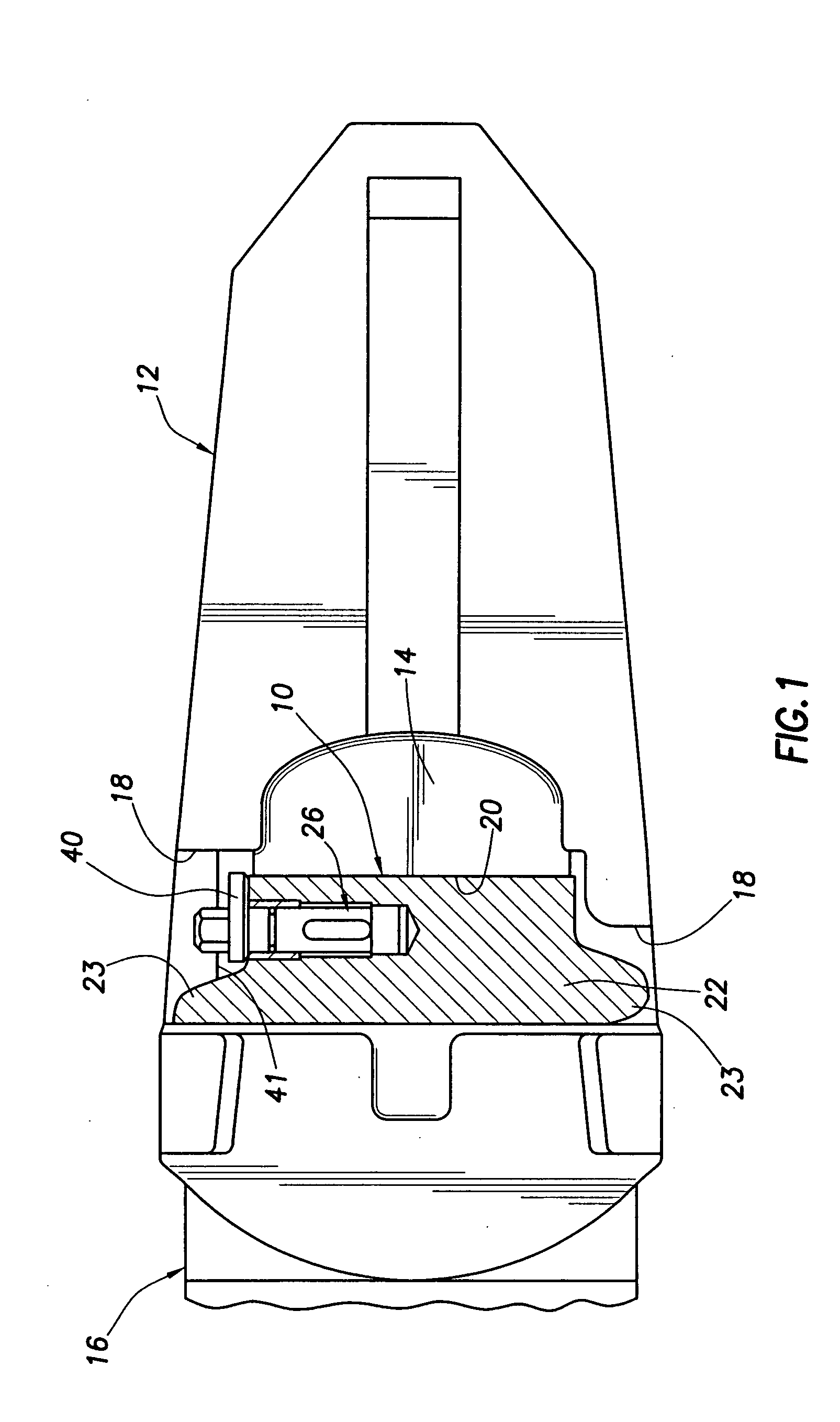
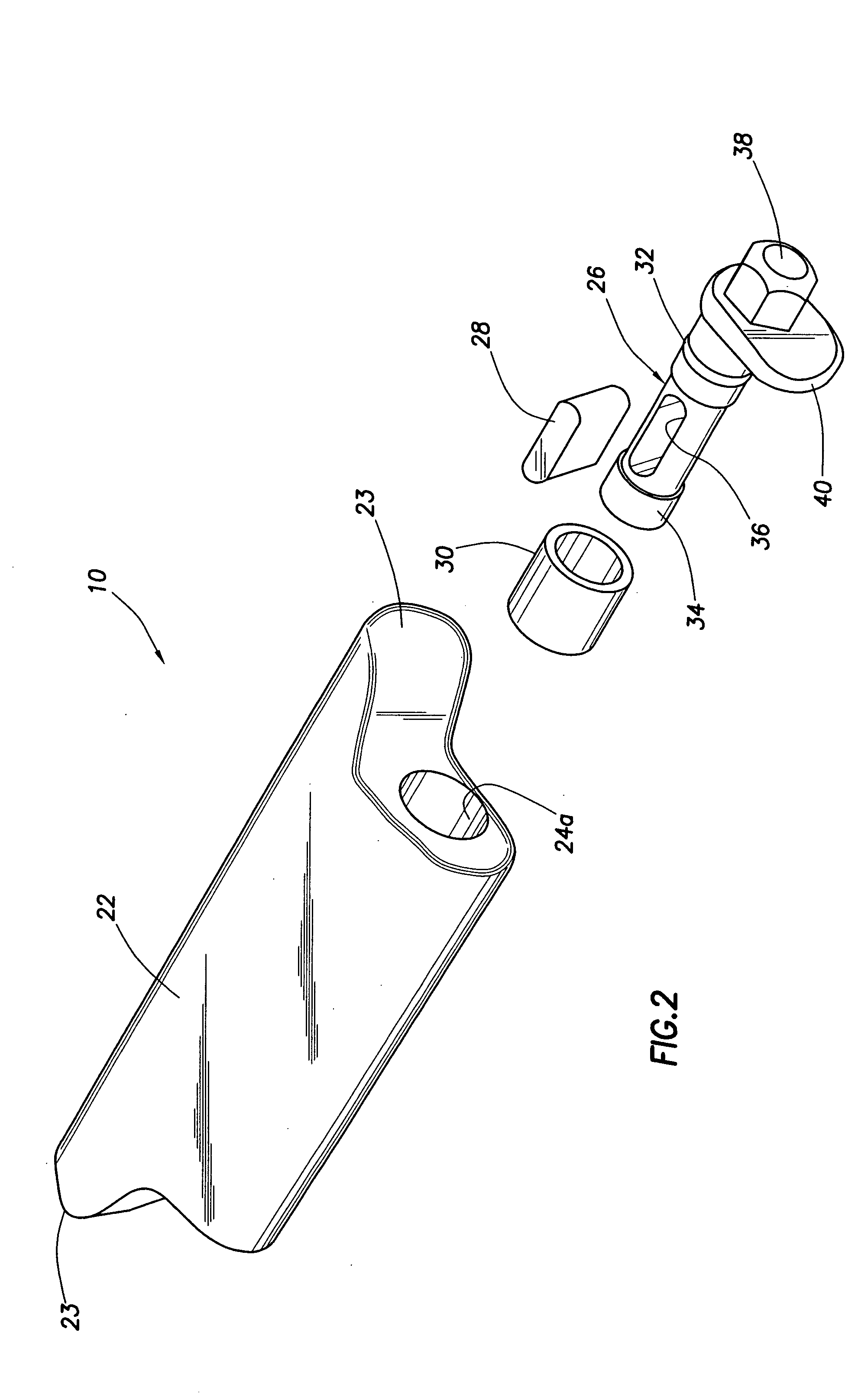
[0023] AS illustrated in FIGS. 1-7, this invention provides a specially designed connector pin assembly 10 which is used to releasably interconnect two telescoped members such as the illustrated excavating tooth point 12 (or other wear member) which is telescoped onto the nose portion 14 of an associated adapter structure 16 (or other support structure). The connector assembly 10 is passed inwardly through aligned connector openings 18,20 respectively formed in the tooth point 12 and the adapter nose 14 and locked therein to block outward removal of the point 12 from the adapter nose 14. For a more detailed description of this general type of excavating equipment connector pin structure, see U.S. Pat. No. 6,108,950 which is assigned to the assignee of the present application and is hereby incorporated herein by reference.

[0024] In addition to its applicability to material displacement and excavating equipment, the connector pin assembly 10 may also be advantageously utilized in joi...


PUM


Abstract

Telescoped excavating support and wear members are releasably retained in their telescoped relationship by a connector pin assembly removably received in aligned connector openings in the members. A body portion of the pin assembly blocks removal of the wear member from the support member, and a lock member portion of the assembly is rotatable relative to the body, toward and away from a locking orientation, to releasably lock the body within the connector openings. A resilient detent member carried by the lock member slidingly and deformably engages a polygonally shaped interior side surface section of a body passage that rotatably receives the lock member, the detent member yieldingly resisting rotational movement of the lock member away from its locking orientation.

Description

BACKGROUND OF THE INVENTION [0001] The present invention generally relates to material displacement apparatus such as excavating equipment and, in illustrated embodiments thereof, more particularly relates to apparatus for releasably coupling a replaceable excavating tooth point or other wear member to an associated adapter nose structure. [0002] A variety of types of material displacement apparatus, such as excavating equipment, are provided with replaceable wear portions that are removably carried by larger base structures and come into abrasive, wearing contact with the material being displaced. For example, excavating tooth assemblies provided on digging equipment such as excavating buckets or the like typically comprise a relatively massive adapter portion which is suitably anchored to the forward bucket lip and has a reduced cross-section, forwardly projecting nose portion, and a replaceable tooth point having formed through a rear end thereof a pocket opening that releasably ...

Claims


Application Information

Patent Timeline
Patent Type & Authority Applications(United States)
IPC IPC(8): E02F9/28
CPCE02F9/2825F16B21/02E02F9/2841E02F9/2833
Inventor RUVANG, JOHN A.ROBINSON, HOWARD W.
Owner HENSLEY INDUSTRIES INC
Learn More