Flying craft camera and sensor mechanized lift platform

a technology of sensor and camera, applied in the field of flying craft, can solve the problems of limited internal and external mounting of cameras and sensors, limited installation specific limitations of externally installed cameras and sensors, so as to achieve efficient transportation of cargo and passengers

Inactive Publication Date: 2005-02-10
LOWE JERRY D +1
View PDF29 Cites 40 Cited by
  • Summary
  • Abstract
  • Description
  • Claims
  • Application Information

AI Technical Summary

Problems solved by technology

Both internally mounted and externally mounted cameras and sensors are limited by their respective installations.
The flying craft interior structure will obstruct image capturing during lateral rotation of the camera.
Externally installed cameras and sensors have a specific set of limitations.
The change in aerodynamic properties resulting from an externally mounted device reduces flying craft performance and increases structural stress and fatigue.
Furthermore, aerial cameras and sensors are expensive.

Method used


Image

  • Flying craft camera and sensor mechanized lift platform
  • Flying craft camera and sensor mechanized lift platform
  • Flying craft camera and sensor mechanized lift platform

Examples


Embodiment Construction

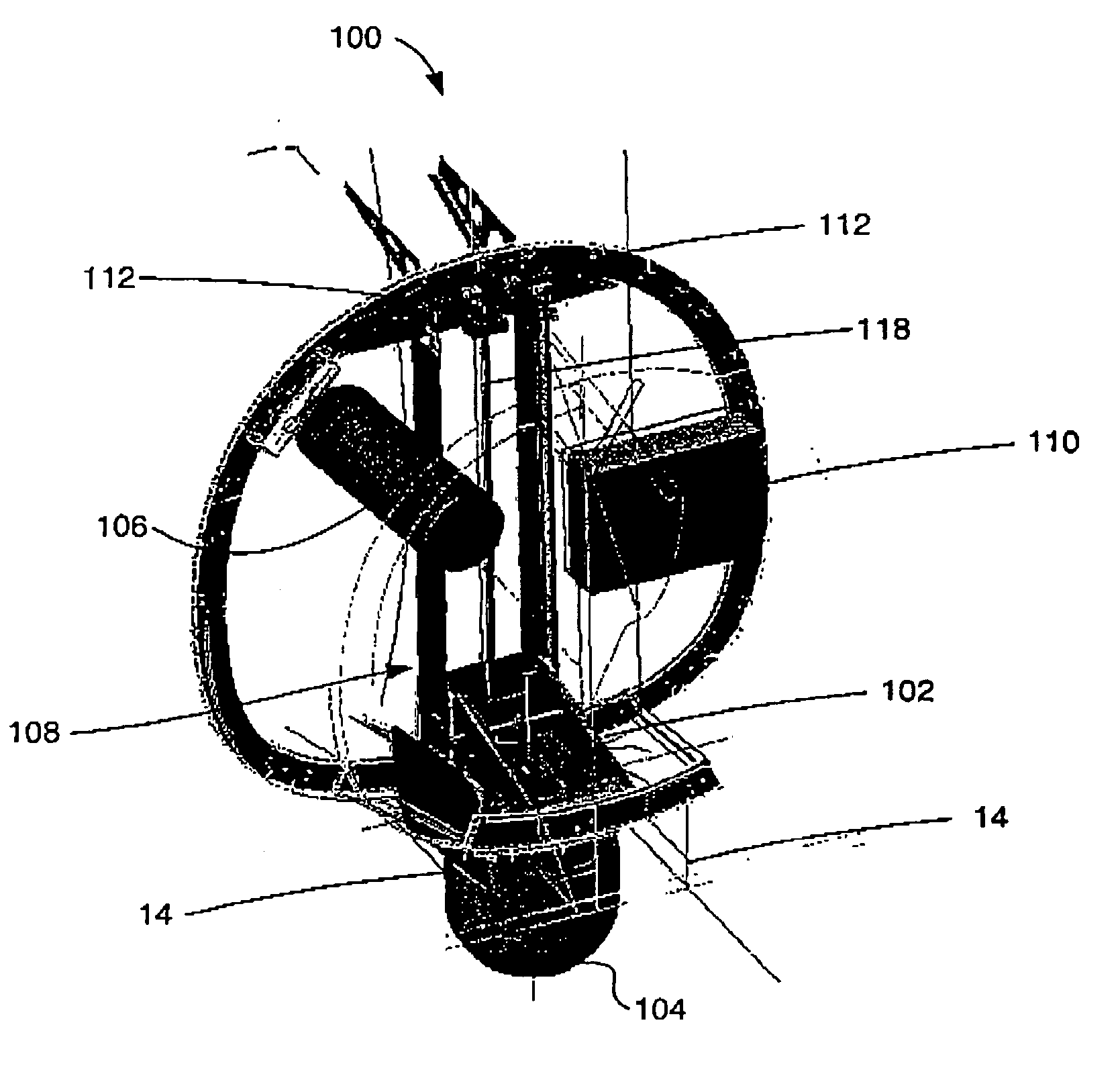
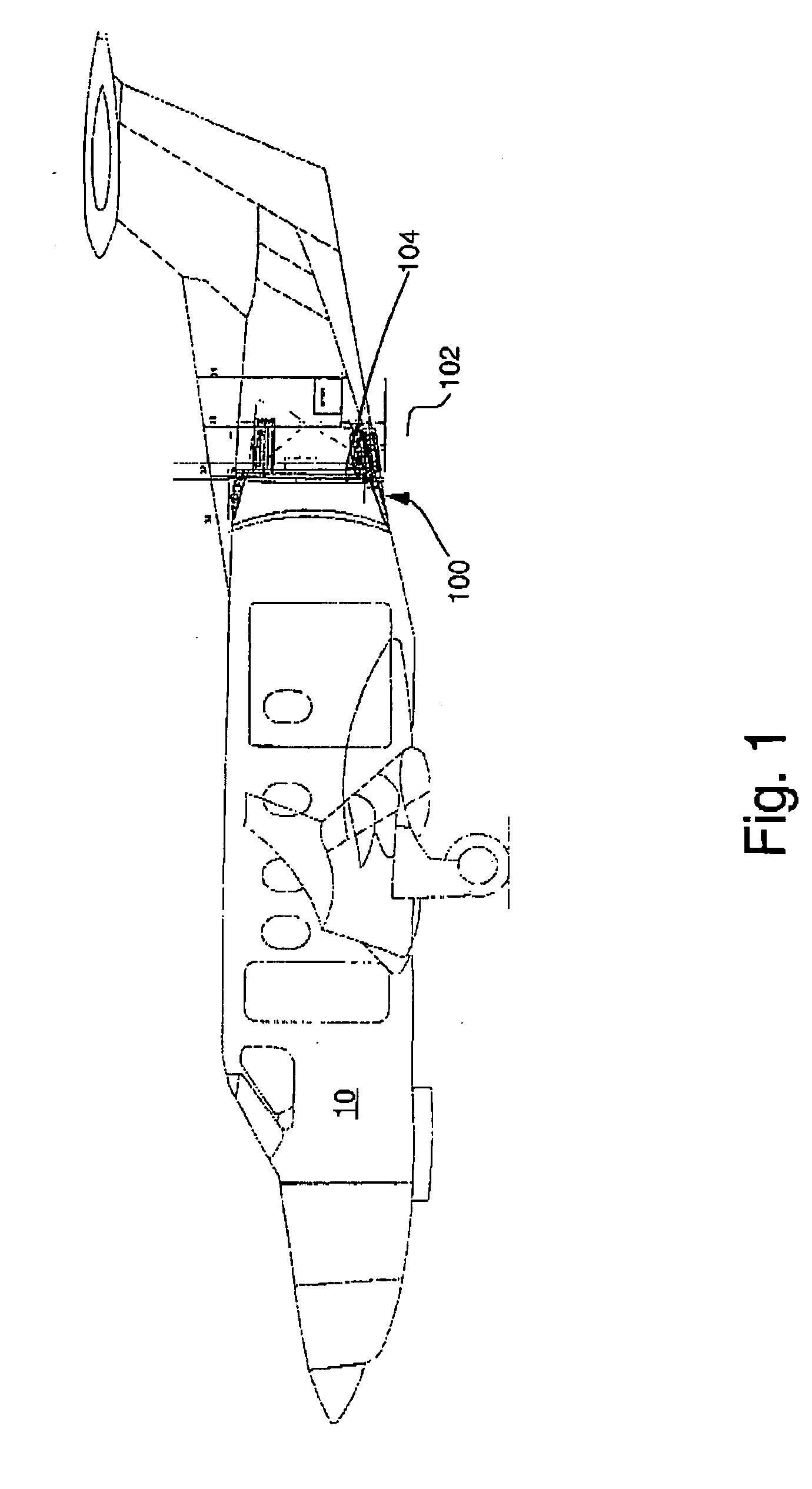
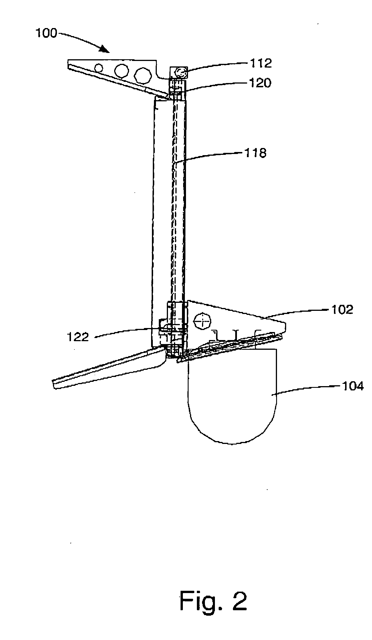
[0013] Now turning to the drawings and more particular to FIG. 1 we have a side view of the lift mechanism installed into an aircraft. This installation is in the tail section, however the mechanism can be installed at any location on the craft. A method of installation comprises the steps of: (1) the lift mechanism (2) a concealment door (3) motor drive (4) mounting surface for the equipment or camera. FIG. 2 shows the lift mechanism using a motor drive system that can be powered by an electric motor, hydraulics, pre-stressed springs, air drive or magnetic drive. FIG. 3 shows that the lift mechanism is mounted to existing structure in the flying craft. The mechanism uses parallel sliding rails to control the platform that the camera is mounted to during the movement of the camera from the stowed position 10 the operating position. The mechanism uses at drive system that is attached to the platform to power the camera into position.


PUM


Abstract

Disclosed herein is a mechanized lift platform for extending a camera and sensor, individually or collectively, out of a flying craft and retracting the camera and sensor back into the flying craft upon completion of use. The camera and sensor in the fully extended position provides a full field of view. The camera and sensor is extended and retracted through concealment doors. The concealment doors are closed when the camera and sensor are in the fully retracted position such that the lift platform and camera and sensor are not subject to any outside environment and the flying craft is able to retain its original flying characteristics. The camera and sensor mechanized lift platform has particular application for aerial photography, video, sound collection and multimedia. A method of capturing images, sounds and data comprising the steps of: Providing a device for extending a camera and sensor outside a flying craft whereby the camera and sensor can be completely retracted into the aircraft, having a platform structure to mount a camera and sensor, a power source, mechanized liner motion structure installed in flying craft to stabilize and guide the camera and sensor mounting platform during extension and retraction, concealment doors to open and close, relay switches to the flying craft cockpit and / or cabin to operate the lift platform and concealment doors, viewing and recording equipment connected to camera and sensor; and opening the concealment doors and extending the camera and sensor during flight to collect images, sounds and data or any combination thereof and display said collected images in a live graphical display in aircraft or to a remote site and upon completion of camera and sensor activities, retracting the lift platform inside the aircraft and closing the concealment doors. In a preferred embodiment of the invention the camera and sensor mechanized lift platform is extended through opened concealment doors during flight to collect images, sounds and data or any combination thereof and upon completion of camera and sensor activities, the lift platform is retracted inside the aircraft and the concealment doors are closed such that the original flying craft speed, maneuverability and aerodynamic characteristics are not altered.

Description

FIELD OF THE INVENTION [0001] This invention relates to flying craft. More particularly this invention relates to a mechanized lift platform that extends and retracts a device for capturing images, sounds and data, individually and collectively, from a flying craft to include but not limited to airplanes, helicopters, blimps, hot air balloons and space crafts. This invention has particular applicability to cameras and sensors installed in flying craft. BACKGROUND OF THE INVENTION [0002] Flying craft are utilized to capture images, sounds and data, individually and collectively. Aerial image, sound and datum capturing devices include cameras and sensors. Aerial cameras and sensors are affixed to the flying craft either internally or externally. Internal cameras and sensors are mounted to the structure inside the body of the flying craft. Internally mounted cameras and sensors are able to capture images, sounds and data using a window, retractable door or permanent opening in the flyi...

Claims


Application Information

Patent Timeline
Patent Type & Authority Applications(United States)
IPC IPC(8): B64D47/08G03B15/00
CPCG03B15/006B64D47/08
Inventor LOWE, JERRY D.DE RUYTER, BRENT K.
Owner LOWE JERRY D
Why Eureka
Try Eureka