
Method and apparatus for measuring a device under test using an improved through-reflect-line measurement calibration

a technology of through reflect line and measurement calibration, which is applied in the direction of measurement devices, resistance/reactance/impedence, instruments, etc., can solve the problems of inability to meet the requirements of through calibration standards. the accuracy of calibration and measurement may not be as accurate as the manufacturer specifications of through calibration standards

Inactive Publication Date: 2005-02-10
AGILENT TECH INC
View PDF13 Cites 124 Cited by
  • Summary
  • Abstract
  • Description
  • Claims
  • Application Information

AI Technical Summary

Problems solved by technology

A through calibration standard is typically unknown for on-wafer calibrations because the landing of the probe to the calibration standard is non-repeatable, which renders the electrical length also non-repeatable, and therefore, unpredictable.
Even though manufacturers of coaxial calibration standards often include electrical length data, over time and after multiple uses, the electrical length can change making a calibration process that relies on the electrical length specifications, less accurate.
Due to machining, process, and other non-repeatable manufacturer variations, the manufacturer specifications of the through calibration standards may not be as accurate as the calibration and measurement presumes.
In addition, frequent use of the through calibration standard can cause the dimensions and, therefore, the calibration specifications to change over time while the calibration process presumes otherwise.
Furthermore, in an on-wafer calibration process, it is difficult to land probes repeatably on a calibration substrate to coincide with the electrical delay value provided by the calibration standard manufacturer.

Method used


Image

  • Method and apparatus for measuring a device under test using an improved through-reflect-line measurement calibration
  • Method and apparatus for measuring a device under test using an improved through-reflect-line measurement calibration
  • Method and apparatus for measuring a device under test using an improved through-reflect-line measurement calibration

Examples


Embodiment Construction

U.S. Pat. No. 5,434,511 entitled “Electronic Microwave Calibration Device” (herein “the '511 patent”) teaches a method for correcting measured S-parameters to arrive at actual S-parameters for a measured device. The method uses twelve error terms calculated from a short-open-load (“SOLT”) calibration process. As one of ordinary skill in the art appreciates, a through-reflect-line (“TRL”) calibration process is also able to determine the twelve error terms from which actual S-parameters are determined based upon measured S-parameters of a device under test. The twelve error terms are: (1) forward directivity (“EDF”), (2) forward source match (“ESF”), (3) forward reflection tracking (“ERF”), (4) forward isolation (“EXR”), (5) forward load match (“ELF”), (6) forward transmission tracking (“ETF”), (7) reverse directivity (“EDR”), (8) reverse source match (“ESR”), (9) reverse reflection tracking (“ERR”), (10) reverse isolation (“EXR”), (11) reverse load match (“ELR”), and (12) reverse tr...


PUM


Abstract

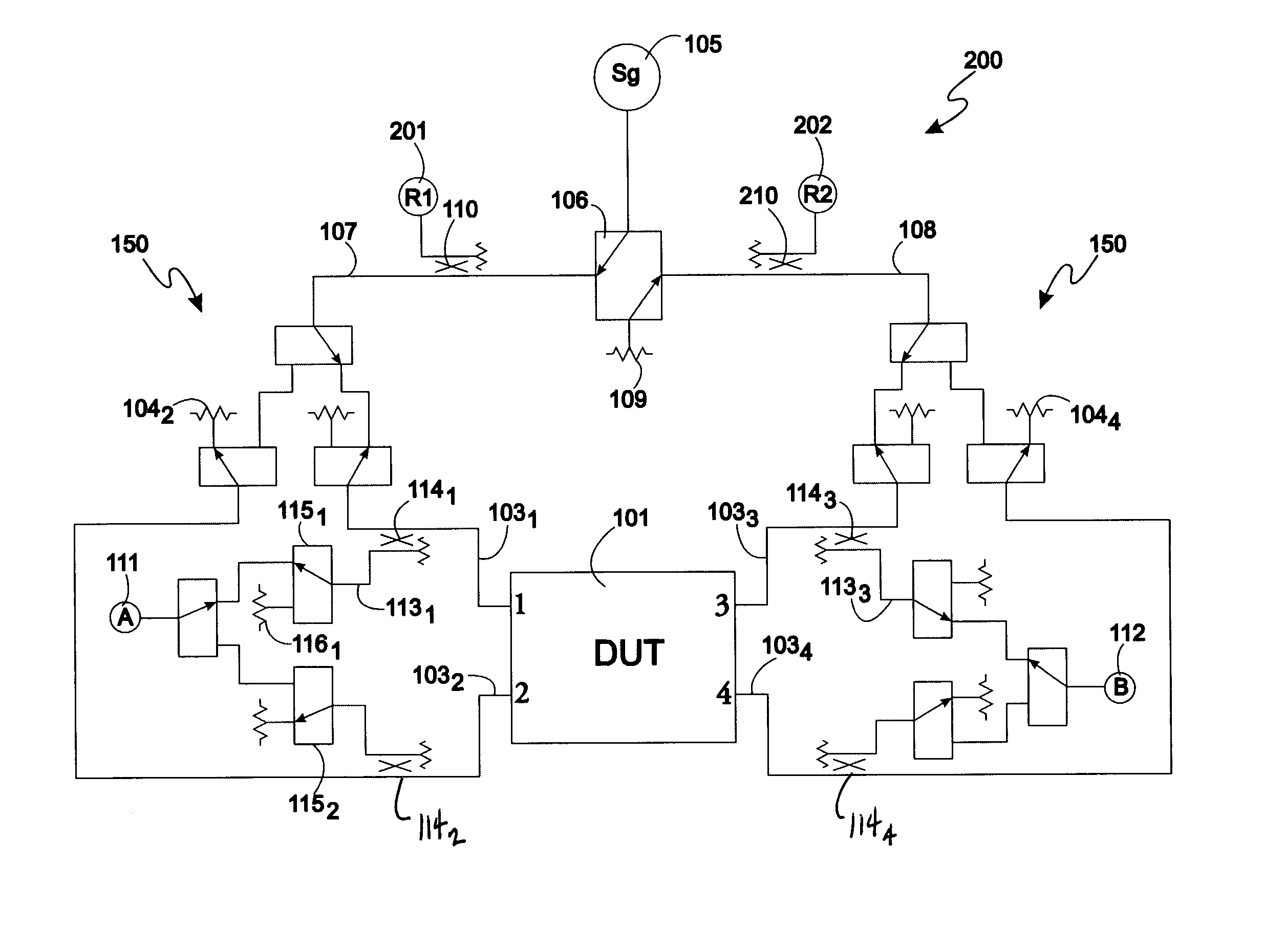
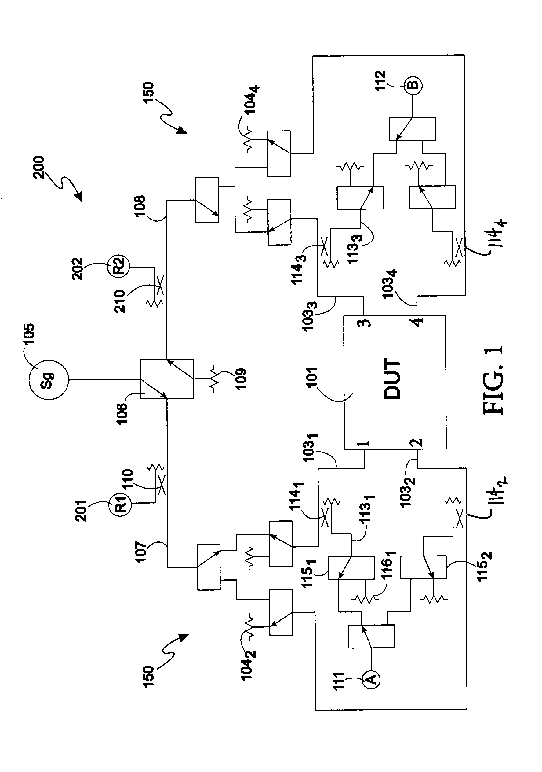
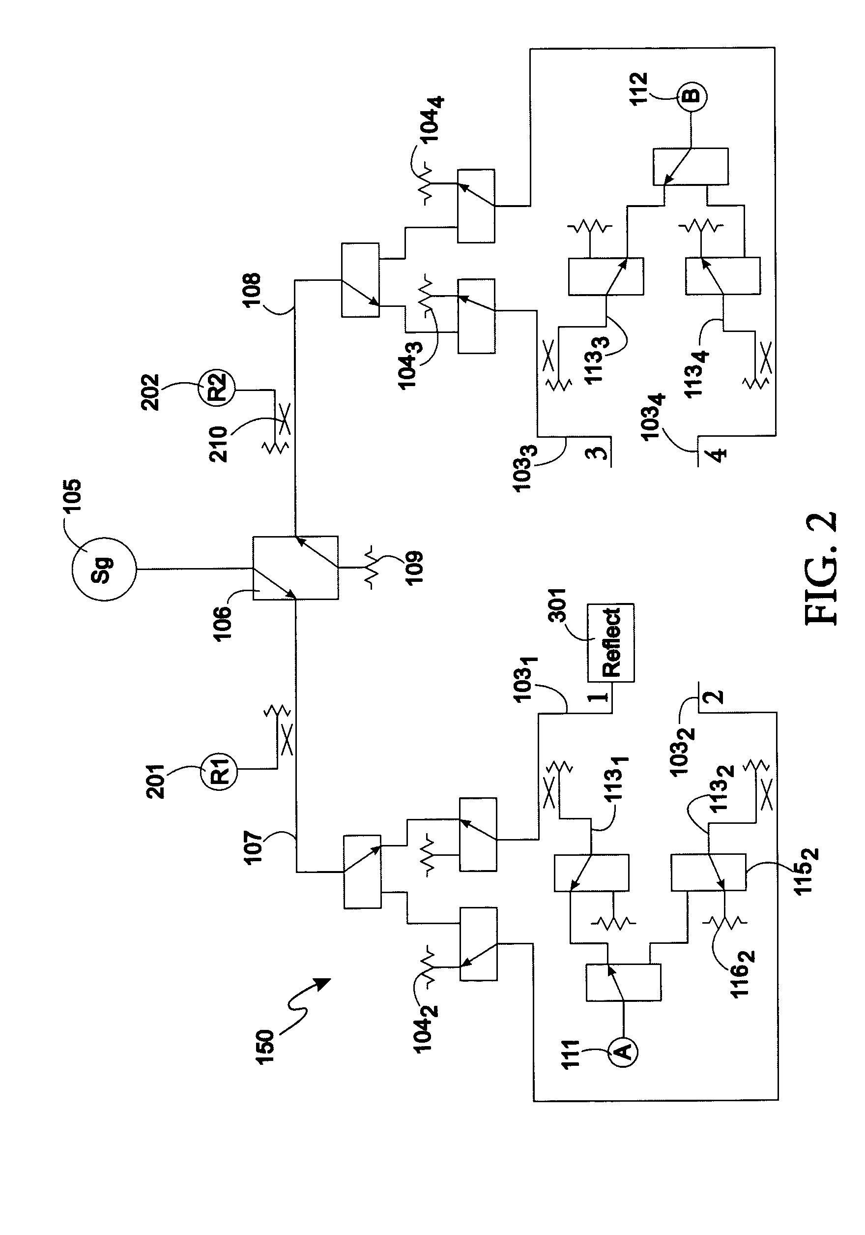
A method and apparatus comprises providing a vector network analyzer having at least two measurement ports and presenting a high reflect calibration standard, a line calibration standard, a source terminated thru calibration standard, and a locally terminated through calibration standard at each measurement port or pair of measurement ports. Forward and reverse reflection tracking is calculated based upon a boundary condition wherein an argument of the reflection tracking coefficients is zero at DC. The DUT is measured and the measurement is corrected for systematic errors based upon the error coefficients.

Description

BACKGROUND U.S. patent application Ser. No. 10 / 294,317 filed Nov. 14, 2002 entitled “Method and Apparatus for Performing Multiport Through-Reflect-Line Calibration and Measurement” (herein “the '317 patent Application”) teaches a method and apparatus for performing a through-reflect-line calibration with a multiple port vector network analyzer (“VNA”). The disclosed method teaches determination of ten-term error coefficients that may be used in a method disclosed in U.S. Pat. No. 5,434,511 (herein “the '511 patent”) to arrive at S-parameters of a device under test (herein “the DUT”) with systematic errors attributable to the VNA and the multiport test set corrected out of the measured S-parameters of the DUT. In the method according to the '317 patent Application, it is necessary to know a type of high reflect calibration standard used in the process. Also, in the method disclosed in the '317 patent Application, if the through calibration standard used in the calibration procedure ...

Claims


Application Information

Patent Timeline
IPC IPC(8): G01R35/00G01R27/06G01R27/28
CPCG01R27/28
Inventor ADAMIAN, VAHE
Owner AGILENT TECH INC
Learn More