Method and system for calibrating projectors to arbitrarily shaped surfaces with discrete optical sensors mounted at the surfaces

a technology of optical sensors and projectors, applied in the field of calibration of projectors to display surfaces, can solve the problems of additional complications and difficulty in determining the correspondence between camera pixels and projector pixels

Inactive Publication Date: 2005-02-10
MITSUBISHI ELECTRIC INFORMATION TECH CENT AMERICA ITA
View PDF5 Cites 103 Cited by
  • Summary
  • Abstract
  • Description
  • Claims
  • Application Information

AI Technical Summary

Benefits of technology

Individual discrete sensors measure the intensity of the projected image at each location directly. Using one or more projected patterns, the system estimates which pixel in the projector's image is illuminating which sensed location.

Problems solved by technology

This is distinguished from camera-based systems that measure light reflected from the surface indirectly, which leads to additional complications.
In camera-based systems it is difficult to determine the correspondences between camera pixels and projector pixels for a number of reasons, including at least different optical properties, different geometries, different resolutions, and different intrinsic and extrinsic parameters.

Method used


Image

  • Method and system for calibrating projectors to arbitrarily shaped surfaces with discrete optical sensors mounted at the surfaces
  • Method and system for calibrating projectors to arbitrarily shaped surfaces with discrete optical sensors mounted at the surfaces
  • Method and system for calibrating projectors to arbitrarily shaped surfaces with discrete optical sensors mounted at the surfaces

Examples


Embodiment Construction

System Structure

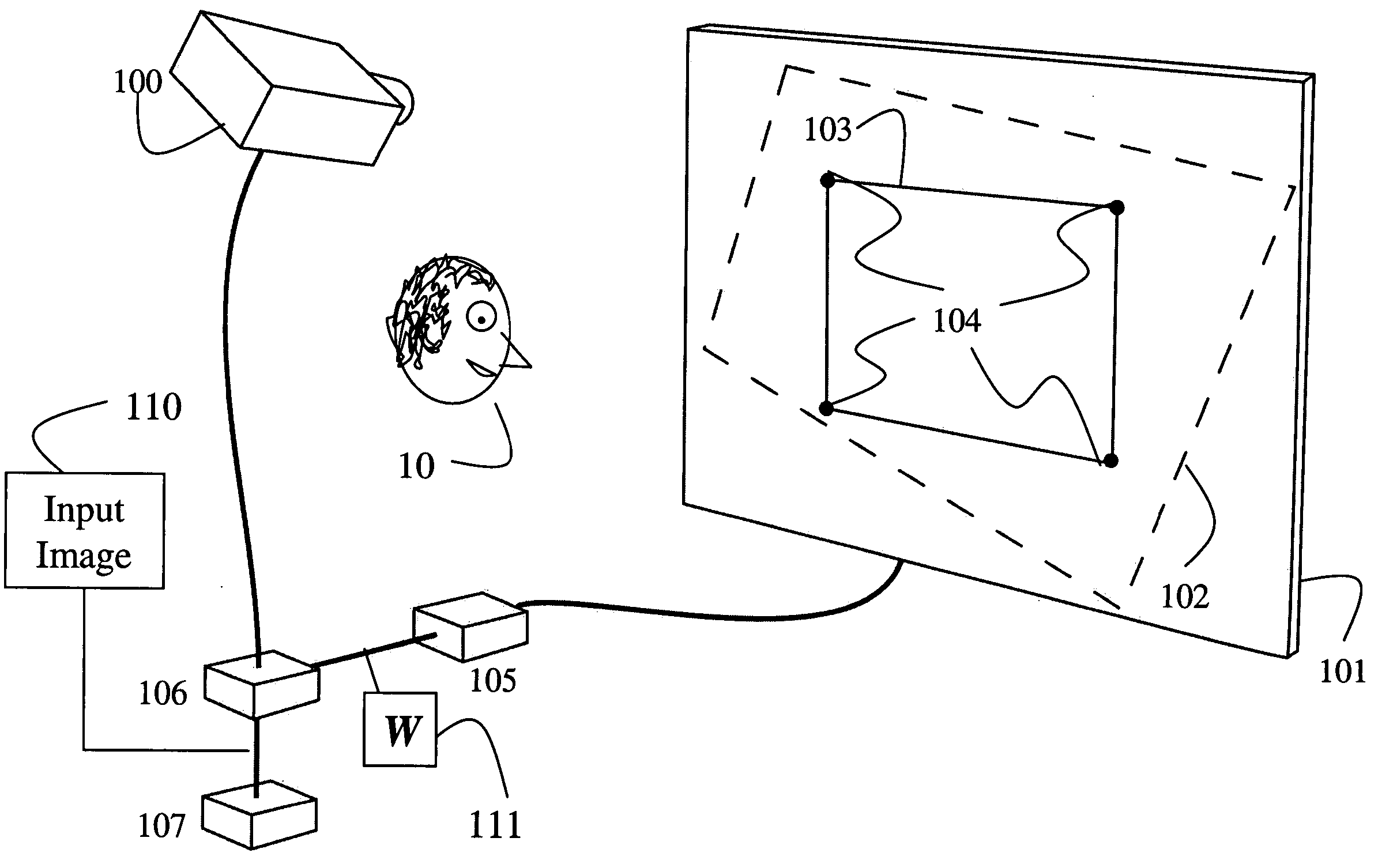
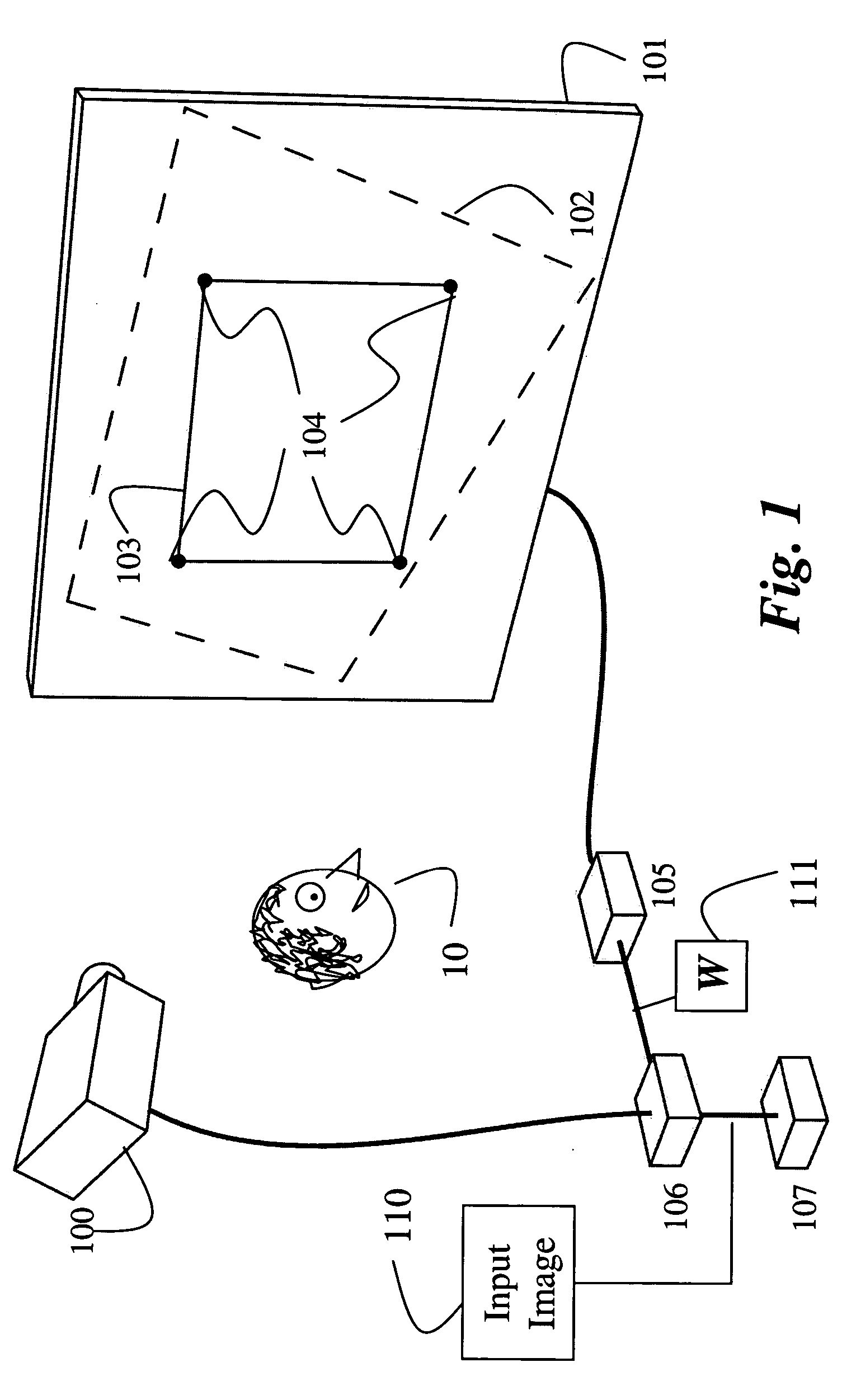
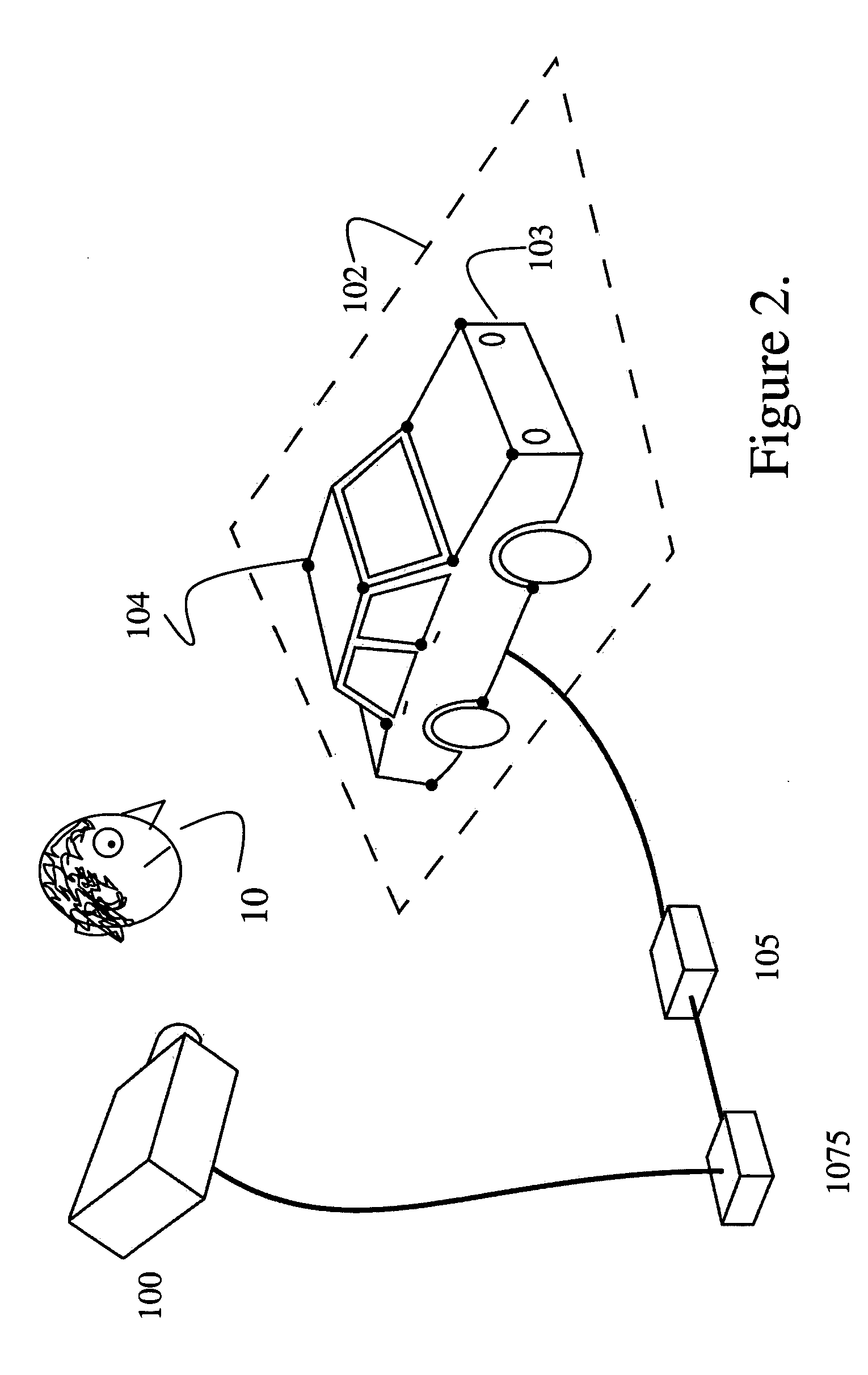
As shown in FIG. 1, a projector 100 is casually aligned with a planar display surface 101. Here, the viewer 10 and the projector 100 are on the same side of the display surface 101. Therefore, the projected images are reflected by the display surface to the viewer. Because of the casual alignment, an output image or video 102 of the projector may not coincide perfectly with a desired image area 103 of the display surface. Therefore, it is necessary to distort an input image 110 so that it conforms to the image area 103 when projected as the output image.

Therefore, the display surface 101 includes four locations 104 with known coordinates, either in 2D or 3D. It should be noted that additional locations could be used depending on a size and topology of the surface 101. Four is a minimum number of locations required to fit the output image to the rectangular image area 103 for an arbitrary projection angle and a planar display surface.

Optical sensors measure an ...


PUM


Abstract

A system determines correspondence between locations on a display surface and pixels in an output image of a projector. The display surface can have an arbitrary shape and pose. Locations with know coordinates are identified on the display surface. Each location is optically coupled to a photo sensor by an optical fiber installed in a throughhole in the surface. Known calibration patterns are projected, while sensing directly an intensity of light at each location for each calibration pattern. The intensities are used to determine correspondences between the of locations and pixels in an output image of the projector so that projected images can warped to conform to the display surface.

Description

FIELD OF THE INVENTION This invention relates generally to calibrating projectors, and more particularly to calibrating projectors to display surfaces having arbitrary shapes. BACKGROUND OF THE INVENTION Portable digital projectors are now common. These projectors can display large format images and videos. Typically, the projector is positioned on a table, located in a projection booth, or mounted on the ceiling. In the prior art, the optical axis of the projectors must be orthogonal to a planar display surface to produce an undistorted image. In addition, a lateral axis of the projector must be horizontal to obtain a level image. Even if the above constraints are satisfied, it is still difficult, or even impossible, given physical constraints of the projection environment, to perfectly align a projected image with a predefined target image area on the projection surface. If the projector is placed causally, then image correction is required. A complete correction for a planar ...

Claims


Application Information

Patent Timeline
Patent Type & Authority Applications(United States)
IPC IPC(8): G03B21/00G03B21/14H04N5/74H04N9/31H04N17/00H04N17/04
CPCH04N9/3185H04N17/04H04N9/3197H04N9/3194
Inventor LEE, JOHNNY CHUNGMAYNES-AMINZADE, DANIELDIETZ, PAUL H.RASKAR, RAMESH
Owner MITSUBISHI ELECTRIC INFORMATION TECH CENT AMERICA ITA
Why Eureka
Try Eureka