SRNS relocation in a UMTS network

a technology of srns relocation and umts network, applied in the field of srns relocation in a umts network, can solve the problems of inconvenient allocation of resources, confusion at the target rnc, and incorrect connection of calls

Inactive Publication Date: 2005-02-10
TELEFON AB LM ERICSSON (PUBL)
View PDF4 Cites 21 Cited by
  • Summary
  • Abstract
  • Description
  • Claims
  • Application Information

AI Technical Summary

Problems solved by technology

The result is that confusion might arise at the Target RNC, with the Target RNC associating RBs with the wrong RABs.
In such a situation, calls may be incorrectly connected and resources allocated inappropriately.

Method used


Image

  • SRNS relocation in a UMTS network
  • SRNS relocation in a UMTS network
  • SRNS relocation in a UMTS network

Examples


Embodiment Construction

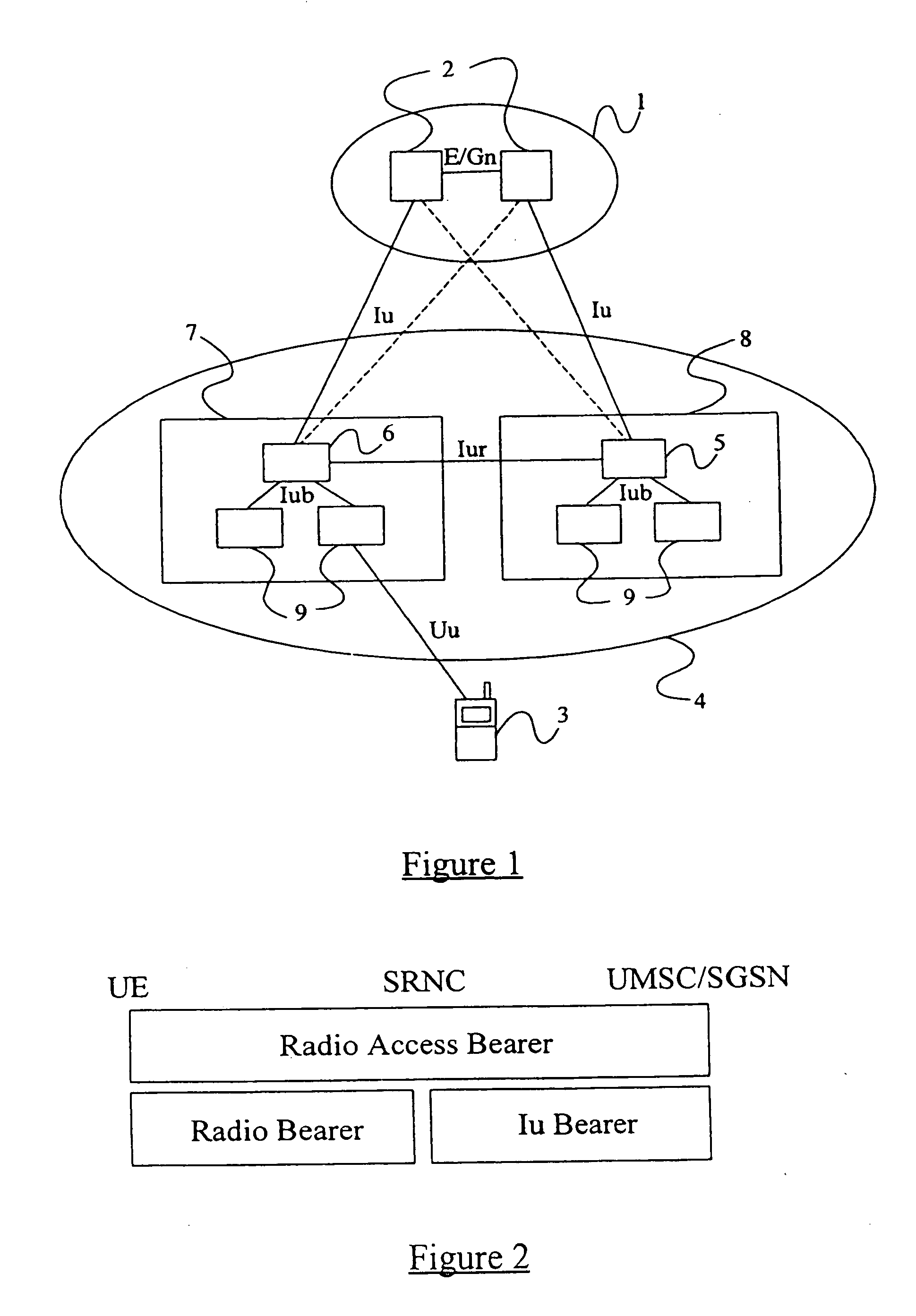
[0022] A typical UMTS network has been described above with reference to FIG. 1, whilst the UTRAN bearer structure employed in such a network has been described with reference to FIG. 2.

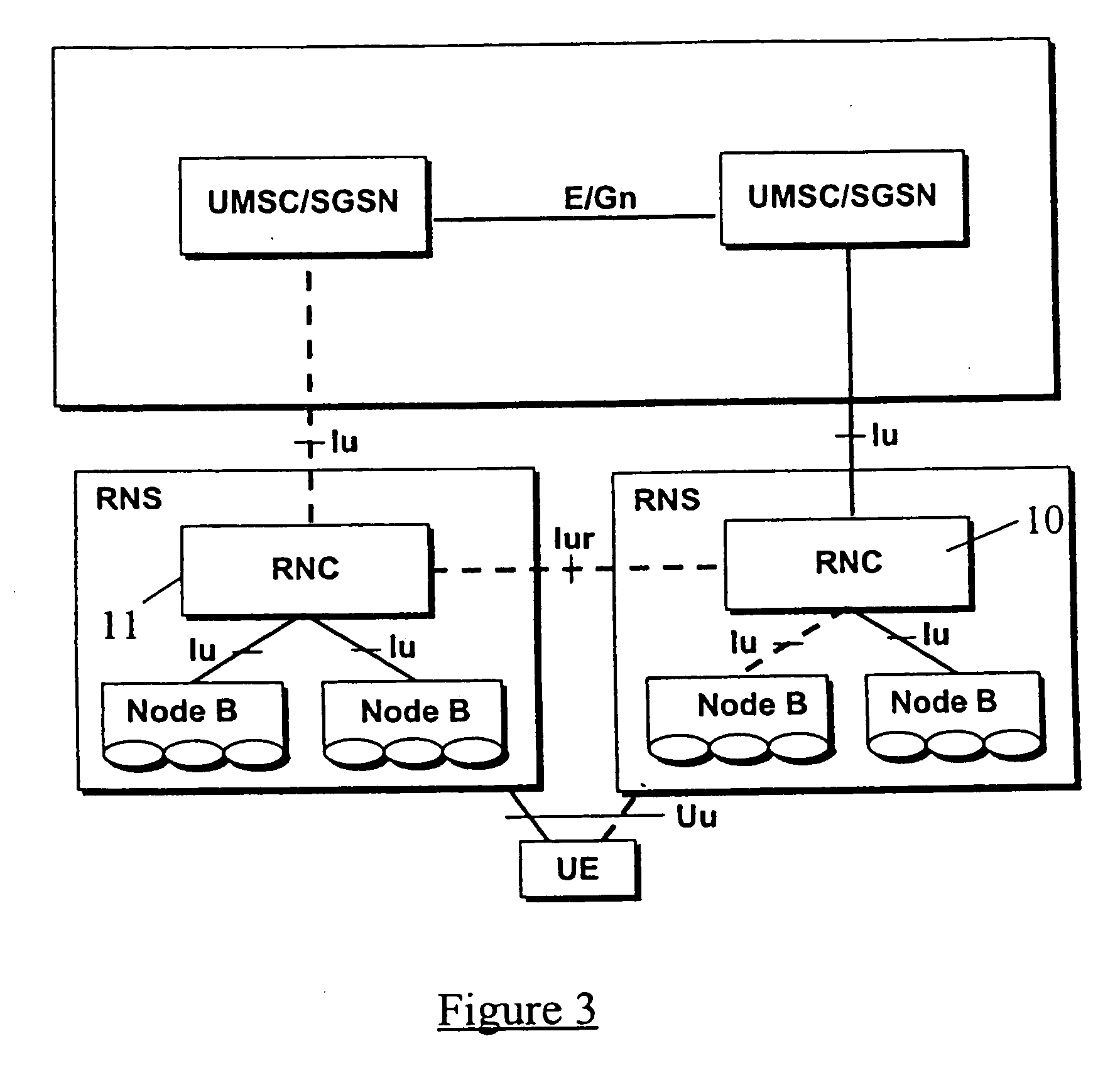
[0023]FIG. 3 illustrates a situation in which User Equipment (UE) is connected to a UMSC / SGSN of a core network of a UMTS network, via a drift RNC 10 and a Serving RNC 11. The “active” connection is illustrated by the broken lines in FIG. 3. Such a situation may arise after the UE has initiated a connection via the Serving RNC 11 and has subsequently moved into the coverage area of the drift RNC 10. FIG. 4 illustrates a situation in which a UE is coupled to a UMSC / SGSN of a core network via only a Serving RNC 11, with the broken lines again illustrating the active connection.

[0024] As described above, under certain circumstances the situation illustrated in FIG. 3 may be a precondition for a SRNS Relocation, where the network decides to transfer the user plane connection between the core network an...


PUM


Abstract

Disclosed is a method and system for performing a Serving Radio Network Subsystem (“SRNS”) Relocation for a given User Equipment (“UE”) in a Universal Mobile Telecommunications System (“UMTS”) network between a UMTS radio network and a UMTS core network, in which the UMTS radio network and the UMTS core network are logically separated, the method comprising: sending a Relocation Required message from the serving Radio Network Controller (“RNC”) to the core network; and sending a Relocation Request message from the core network to the Target RNC.

Description

FIELD OF THE INVENTION [0001] The present invention relates to SRNS Relocation in a UMTS network and more particularly to the transfer of radio resources between a SRNS and a target RNS during such Relocation. BACKGROUND TO THE INVENTION [0002]FIG. 1 illustrates schematically a part of a Universal Mobile Telecommunications System (UMTS) network. The network includes a core network part 1, which may be a network handling voice calls using UMTS Mobile-services Switching Centres (UMSCs) or may be a data network such as a General Packet Radio Service (GPRS) network including Serving GPRS Support Nodes (SGSNs). In FIG. 1 the UMSCs and SGSNs are indicated generally with the reference numeral 2. A subscriber or User Equipment (UE) 3 is coupled to the core network 1 via an access network 4 referred to as a Universal Terrestrial Radio Access Network (UTRAN). More particularly, the UMSCs / SGSNs 2 are connected to Radio Network Controllers (RNCs) 5,6 of the UTRAN 4 over an interface referred to...

Claims


Application Information

Patent Timeline
Patent Type & Authority Applications(United States)
IPC IPC(8): H04W36/12H04M3/00
CPCH04W36/12H04W36/10
Inventor LAIHO, KEIJOSIMONEN, SATU
Owner TELEFON AB LM ERICSSON (PUBL)
Why Eureka
Try Eureka