
Image reproducing device

Inactive Publication Date: 2005-02-10
MITSUBISHI ELECTRIC CORP
View PDF4 Cites 9 Cited by
  • Summary
  • Abstract
  • Description
  • Claims
  • Application Information

AI Technical Summary

Benefits of technology

[0008] The present invention has been accomplished to solve the above-mentioned problem. An object of the present invention is to provide an image reproducing device that can ensure sufficient vibration resistance because a reproducing unit and a display monitor therein can be positively locked and held at the folding / storing position of the unit and the monitor even if the device receives a strong impact or vibration while the vehicle is moving.
[0009] Another object of the present invention is to provide an image reproducing device in which the electromagnetic shielding of its reproducing unit can be improved.
[0010] Still another object of the present invention is to provide an image reproducing device in which the cooling efficiency of its reproducing unit can be improved.
[0013] Furthermore, the image reproducing device according to another aspect of the present invention may be arranged to include: a second post-pin locking means for mechanically locking a post pin, which is protrusively provided on the side of the reproducing mechanism built-in box, at the folding / storing position of the box in association with the folding / developing operation of the reproducing mechanism built-in box; and a common lock release actuating mechanism that causes the second post-pin locking means and the image-display-unit locking means to simultaneously perform a lock-releasing operation. As a result, according to the aspect of the present invention, simply causing the image display unit and the reproducing mechanism built-in box to perform the folding operation or the developing operation enables the image display unit and the reproducing mechanism built-in box to be strongly locked or held in an automatic-mechanical manner at their respective folding / storing positions. Accordingly, this can eliminate the uncontrollable vibration or descending rotation of the reproducing mechanism built-in box and the image display unit placed in the folding / storing state, which are caused by the influence of the violent shock and vibration of a mobile unit such as a vehicle. Thereby, the image reproducing device can obtain high vibration resistance with high reliability.
[0014] Moreover, the image reproducing device according to another aspect of the present invention can be arranged such that the reproducing mechanism built-in box is made of a sheet metal box. As a result, according to the aspect of the present invention, the reproducing mechanism housed in the reproducing mechanism built-in box can be efficiently electromagnetically shielded, thereby greatly improving the electromagnetic shielding characteristics of the mechanism.
[0015] Furthermore, the image reproducing device according to still another aspect of the present invention can be arranged such that the image reproducing device has a fan that is secured at the rear end of the reproducing mechanism built-in box, and ventilates the inside of the box; and a cover member that has a window hole permitting the rotation of the image display unit and the reproducing mechanism built-in box, and is secured on the chassis; and in the cover member is provided an air passage that exhausts the air taken in by the fan to the outside. As a result, according to the aspect of the present invention, the heat generated in the reproducing mechanism built-in box can be exhausted to the outside with the fan. Therefore, the inside of the reproducing mechanism built-in box can be efficiently cooled.

Problems solved by technology

Since the conventional image reproducing device is arranged as mentioned above, there is the following problem.
However, when the reproducing unit and display monitor receive a strong vibration, they cannot resist the vibration, to thereby be shaken.
This results in the detachment of the leaf spring from the shallow engaging concavity, thereby violently vibrating the reproducing unit up and down.
Thus, there is a problem that the image reproducing device cannot have sufficient vibration resistance.

Method used


Image

  • Image reproducing device
  • Image reproducing device
  • Image reproducing device

Examples


first embodiment

[0031] First Embodiment

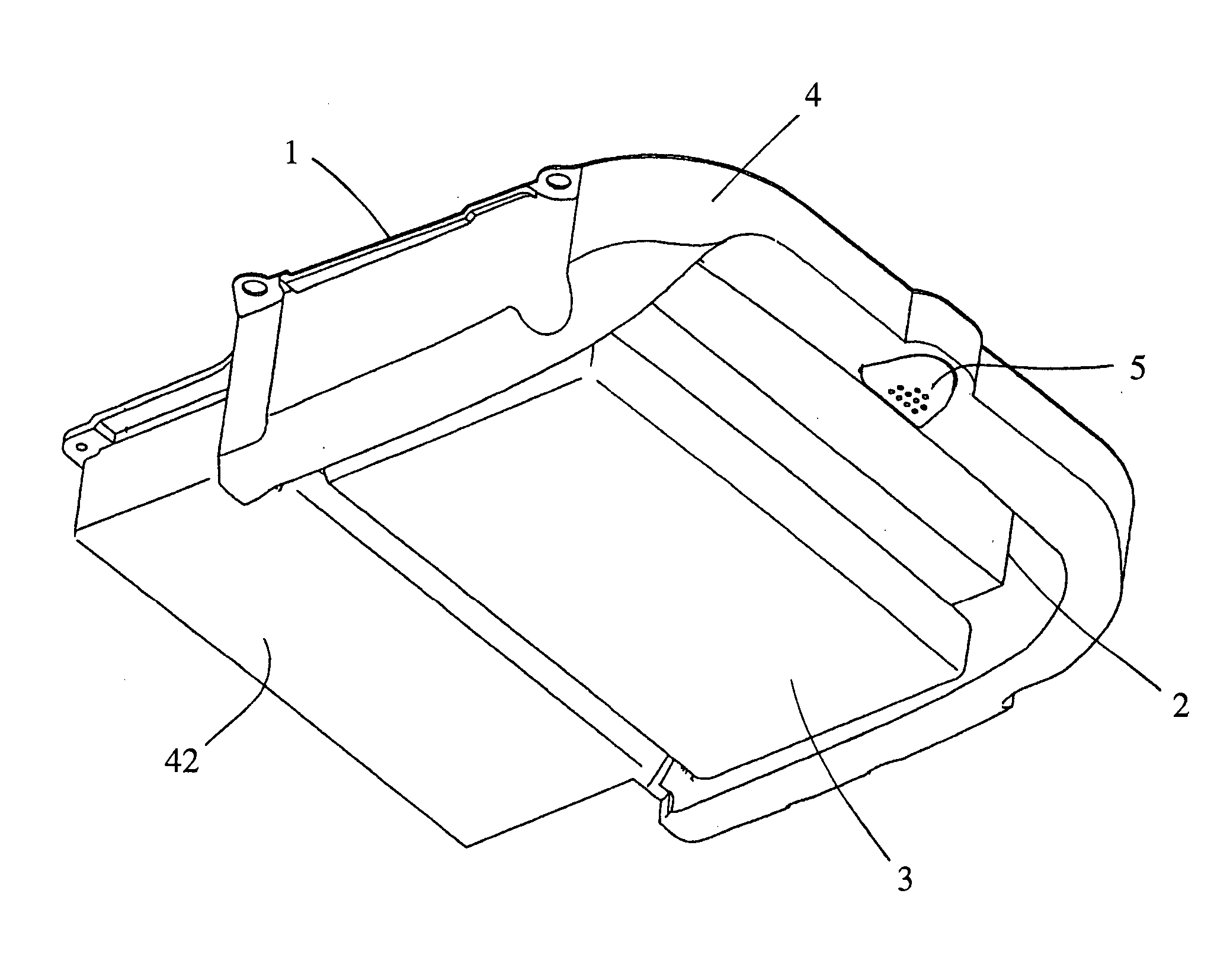
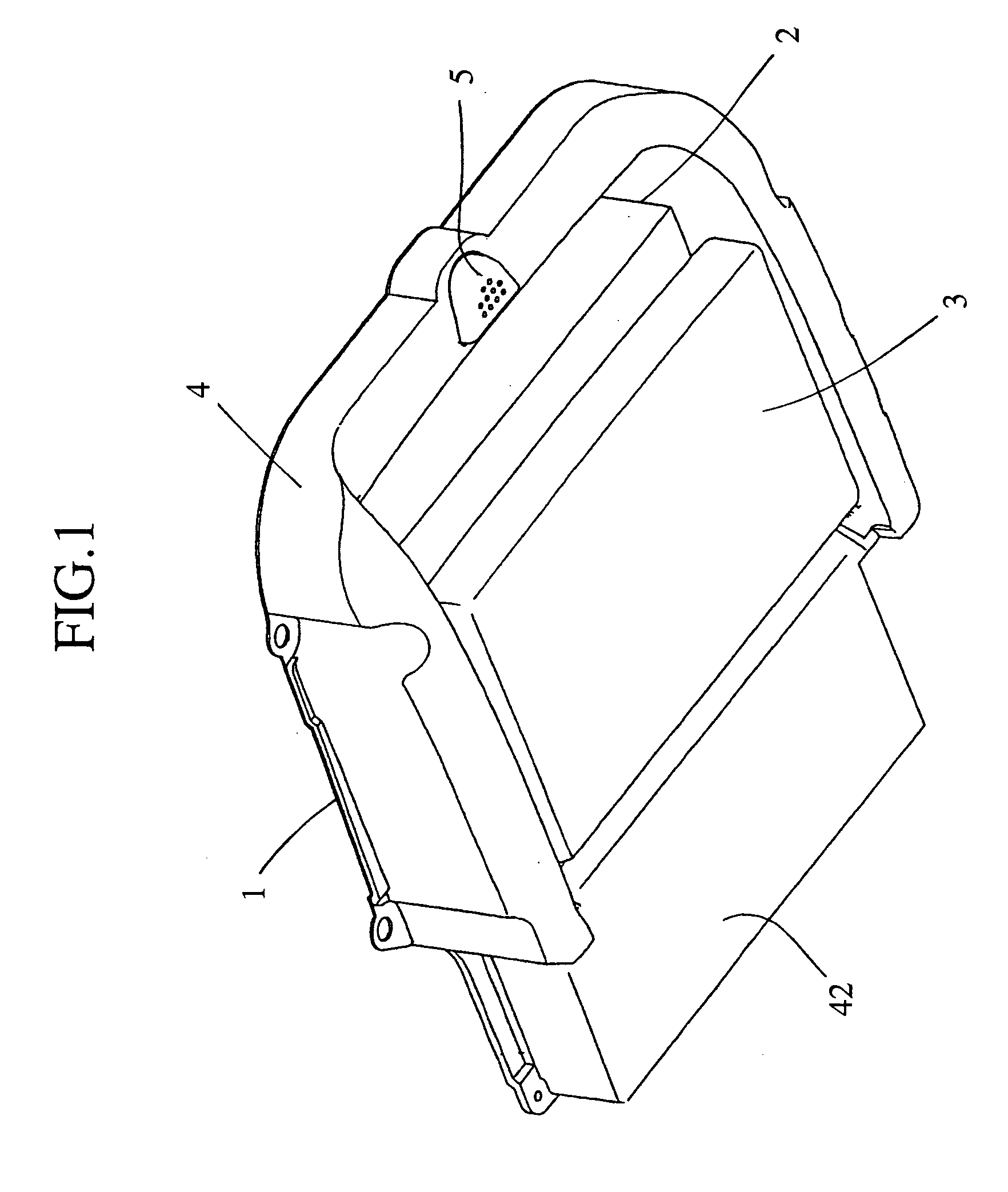
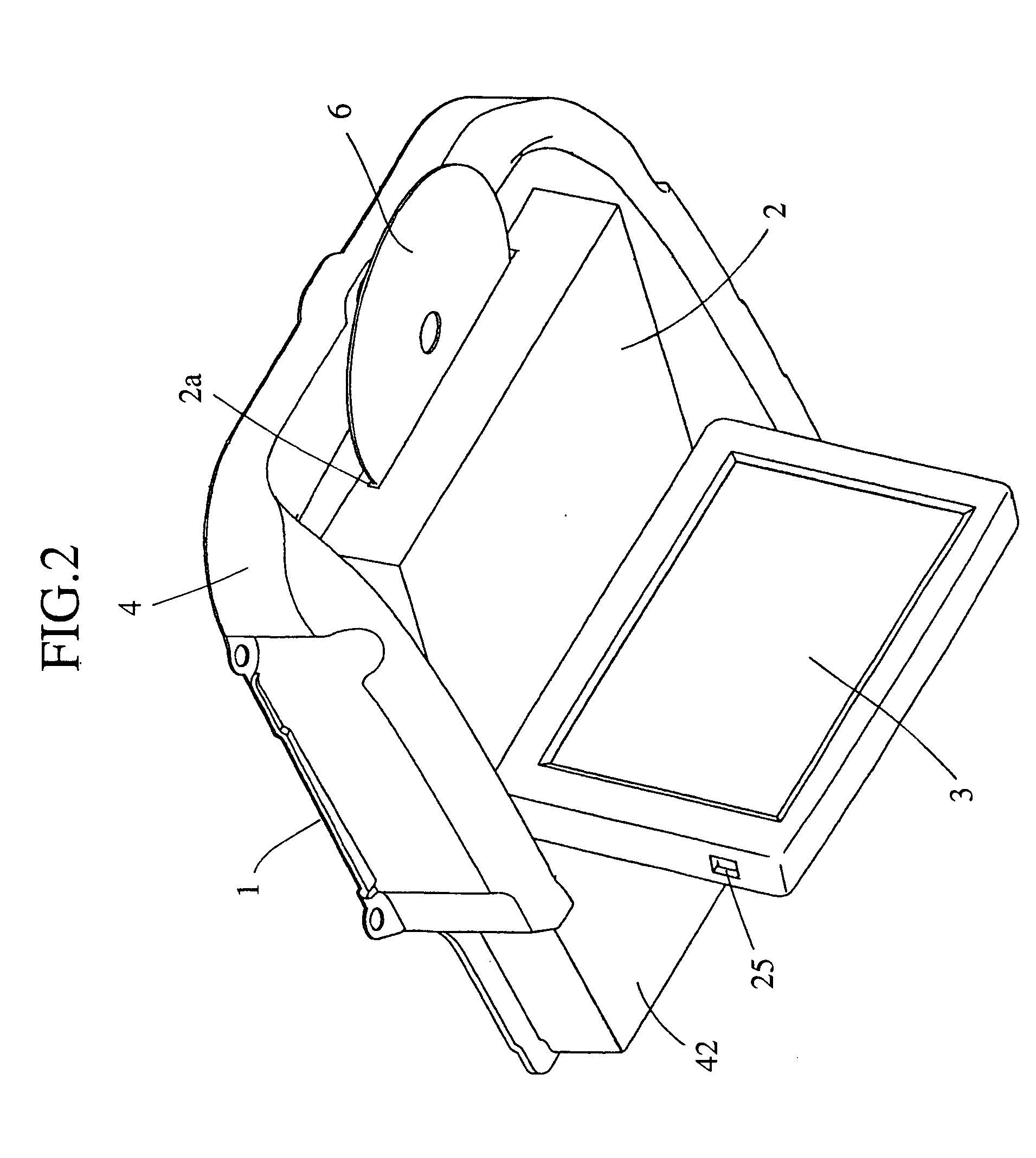
[0032]FIG. 1 is an appearance perspective view of the state in which an image reproducing device according to a first embodiment of the present invention is folded. FIG. 2 is an appearance perspective view of the state in which the image reproducing device shown in FIG. 1 is opened and developed.

[0033] The image reproducing device according to the first embodiment can be arranged such that a reproducing mechanism built-in box 2 having a built-in reproducing mechanism such as a DVD player, a display monitor (image display unit) 3, and a cover member 4 are assembled to a plate-shaped chassis 1 secured on the ceiling surface of the room of mobile units such as a variety of vehicles or ships. The reproducing mechanism built-in box 2 and the display monitor 3 are arranged to be locked at the folded and stored position shown in FIG. 1. The locking mechanism therefor will be described later. The reproducing mechanism built-in box 2 and the display monitor 3 are arra...


PUM


Abstract

An image reproducing device has a post pin that is protrusively provided on a reproducing mechanism built-in box, a first post-pin locking mechanism that locks the post pin at the folding position of the reproducing mechanism built-in box by the folding / developing operation of the box, a second post-pin locking mechanism that responds to the operation of an image display unit to lock the post pin at the developing position of the reproducing mechanism built-in box, an image-display-unit locking mechanism in association with the folding operation of the image display unit to lock the image display unit at the storing position of the unit, and a common lock release actuating mechanism that simultaneously releases the lock of the first post-pin locking mechanism and the lock of the image-display-unit locking mechanism.

Description

BACKGROUND OF THE INVENTION [0001] 1. Field of the Invention [0002] The present invention relates to an image reproducing device secured to the ceiling surface of the room of a mobile unit such as a vehicle to reproduce and display image information. [0003] 2. Description of the Related Art [0004] As this type of the image reproducing device, for example, WO 02 / 09976 A1 (FIG. 3 and FIG. 4) discloses an image reproducing device including a display monitor (image display unit) and a reproducing unit such as a DVD player; these display monitor and reproducing unit are rotatably supported by a common rotating shaft in the folding / developing direction with respect to a chassis; the chassis is secured on the ceiling surface of the vehicle room; when using the device, the display monitor is downwardly opened, responsively followed by the reproducing unit to be opened to a position where a disk-inserting inlet comes to a DVD-insertable slanted angle, whereas when not using the device, the d...

Claims


Application Information

Patent Timeline
IPC IPC(8): B60R11/02G09F9/00G11B33/02G11B33/10H04N5/64H04N5/91
CPCG11B33/10G11B33/022
Inventor IKUNAMI, TAKAHIRO
Owner MITSUBISHI ELECTRIC CORP
Learn More