
Hand activated ultrasonic instrument

a technology of ultrasonic instruments and hands, applied in the field of ultrasonic surgical clamp coagulator apparatus, can solve the problems of surgeon leg fatigue, foot pedal getting, surgeon fatigue, etc., and achieve the effect of promoting convenient and efficient use of the apparatus

Inactive Publication Date: 2005-02-10
CILAG GMBH INT +1
View PDF6 Cites 372 Cited by
  • Summary
  • Abstract
  • Description
  • Claims
  • Application Information

AI Technical Summary

Benefits of technology

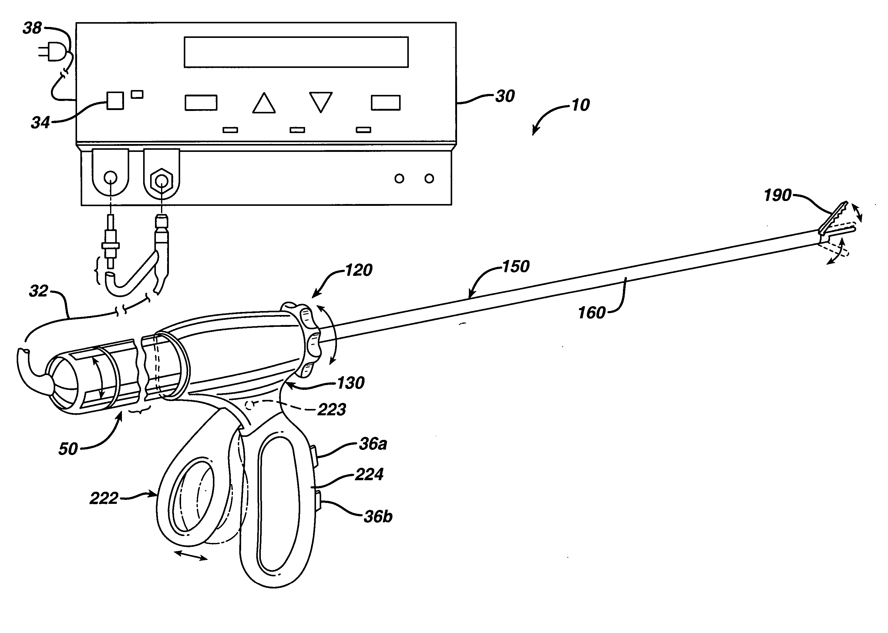
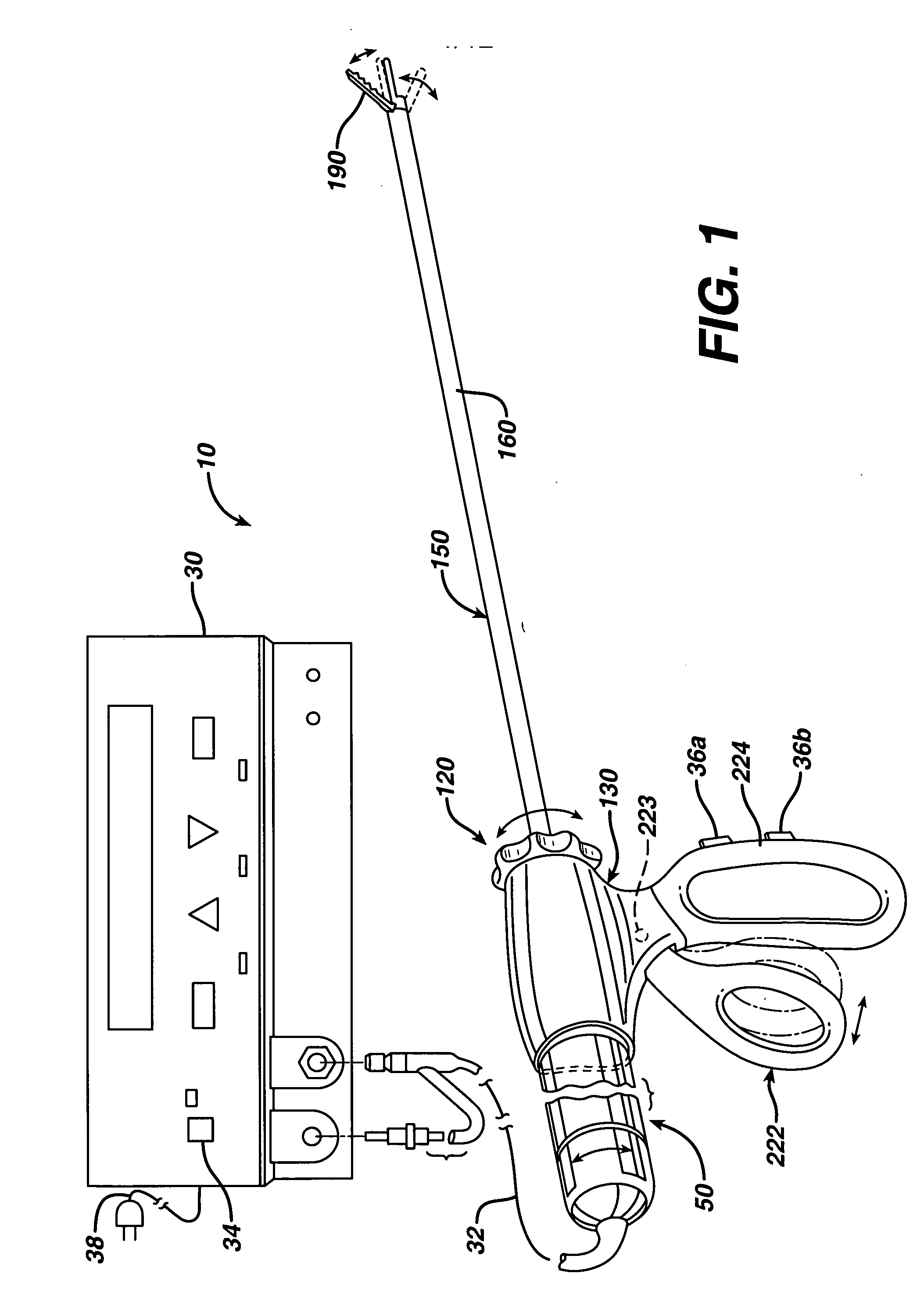
[0008] An ultrasonic surgical clamp coagulator apparatus embodying the principles of the present invention is configured to permit hand activation for cutting, coagulation, and clamping of tissue during surgical procedures. In order to promote convenient and efficient use of the apparatus, the fingertip controls are provided directly into the disposal shears handle in a position that allows surgeons to activate the device without repositioning their hand. The two buttons provide independent control of the two power levels available from the generator, matching the two-foot pedal configuration.
[0009] In one embodiment the buttons are a rocker style configuration where the buttons appear independent to the user, but are actually a single unit rotating about a central axis. This configuration eliminates dual activation of the buttons, which would cause an error condition at the generator. The buttons are also incorporated in a manner in which the angle of depression / activation is not parallel, but rather, angled toward a common point in space to improve ergonomic feel. Further, the buttons are spaced to allow the user to rest their trigger finger (e.g. the index finger) between the buttons. This configuration minimizes the opportunity of an inadvertent activation and provides a high degree of grip stability during grasping and manipulation of tissue. In combination with the rocker switch are dome switches integrated within a flex circuit to provide for the electrical contact and snap feel of the rocker switches.
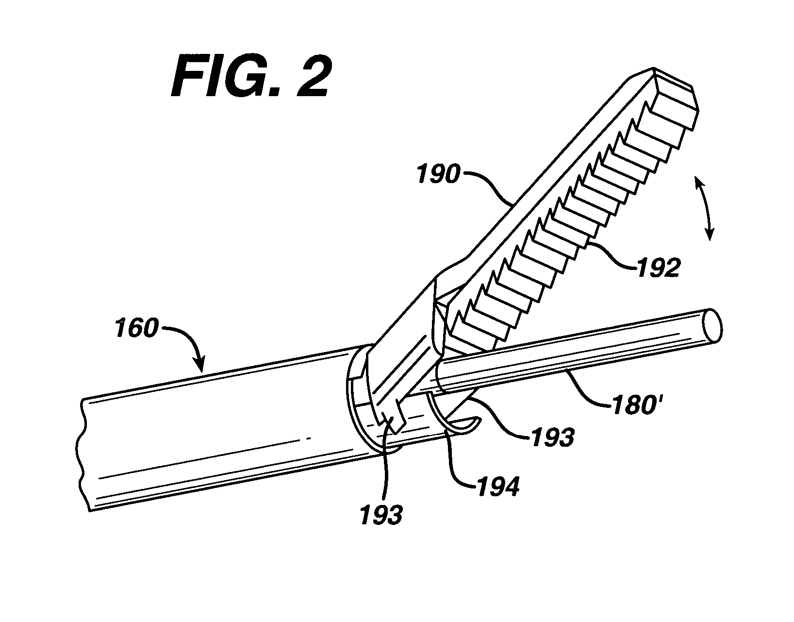
[0013] An operating lever pivotally connected on the apparatus housing provides selective operation of the apparatus clamping mechanism. In the preferred embodiment, the operating lever, and associated handgrip portion of the housing are provided with a pistol-like configuration, thus permitting convenient movement of the operating lever by a user's thumb. The operating lever is interconnected with the reciprocal actuating member by a clamp drive mechanism so that pivotal movement of the operating lever reciprocally moves the actuating member for pivotally moving the clamp arm of the apparatus. Notably, the handgrip portion includes two pushbuttons for activating the end-effector, thus permitting the end-effector to be selectively activated by the surgeon's fingertip.

Problems solved by technology

Key drawbacks with this type of instrument activation include the loss of focus on the surgical field while the surgeon searches for the foot pedal, the foot pedal getting in the way of the surgeon's movement during a procedure and surgeon leg fatigue during long cases.

Method used


Image

  • Hand activated ultrasonic instrument
  • Hand activated ultrasonic instrument
  • Hand activated ultrasonic instrument

Examples


Embodiment Construction

[0025] Before explaining the present invention in detail, it should be noted that the invention is not limited in its application or use to the details of construction and arrangement of parts illustrated in the accompanying drawings and description. The illustrative embodiments of the invention may be implemented or incorporated in other embodiments, variations and modifications, and may be practiced or carried out in various ways. Furthermore, unless otherwise indicated, the terms and expressions employed herein have been chosen for the purpose of describing the illustrative embodiments of the present invention for the convenience of the reader and are not for the purpose of limiting the invention.

[0026] The present invention is particularly directed to an improved ultrasonic surgical clamp coagulator apparatus which is configured for effecting tissue cutting, coagulation, and / or clamping during surgical procedures. The present apparatus can readily be configured for use in both ...


PUM


Abstract

An ultrasonic surgical clamp coagulator apparatus is configured to effect cutting, coagulation, and clamping of tissue by cooperation of a clamping mechanism of the apparatus with an associated ultrasonic end-effector. The handle of the apparatus is configured to permit hand activation for cutting, coagulation, and clamping of tissue during surgical procedures. In order to promote convenient and efficient use of the apparatus, the fingertip controls are provided directly into the disposal shears handle in a position that allows surgeons to activate the device without repositioning their hand. The two buttons provide independent control of the two power levels available from the generator, matching the two foot pedal configuration of the prior art.

Description

REFERENCE TO RELATED APPLICATIONS [0001] The present application claims the priority benefit of U.S. provisional patent application Ser. No. 60 / 478,984, filed on Jun. 17, 2003, which is incorporated herein by reference. [0002] This application contains subject matter related to co-owned patent application Ser. Nos. 09 / 879,319 and 09 / 693,549, both of which are hereby incorporated herein by reference.FIELD OF THE INVENTION [0003] The present invention relates generally to ultrasonic surgical devices, and more particularly to an ultrasonic surgical clamp coagulator apparatus for coagulating and / or cutting tissue, including a hand activated switch positioned on the handle for easy access by the surgeon. BACKGROUND OF THE INVENTION [0004] Ultrasonic surgical instruments are finding increasingly widespread applications in surgical procedures by virtue of the unique performance characteristics of such instruments. Depending upon specific instrument configurations and operational parameters...

Claims


Application Information

Patent Timeline
IPC IPC(8): A61B17/00A61B17/32A61L
CPCA61B17/320092A61B2017/00017A61N7/00A61B2017/0046A61B18/00A61B2017/00367A61B2017/320095A61B2017/320093A61B2017/320094
Inventor MUIR, STEPHANIE J.PROCH, FRANCIS S.DUTTA, SUDEEP N.KRAMER, KENNETH S.
Owner CILAG GMBH INT
Learn More