
Collision prediction apparatus

a technology of collision prediction and apparatus, which is applied in the direction of electric devices, navigation instruments, jet propulsion mountings, etc., can solve the problems of occupant protection (supporting) apparatus performing useless operations and erroneously recognizing collision objects, so as to improve the accuracy of predictive collision determination

Inactive Publication Date: 2005-02-10
TOYOTA JIDOSHA KK
View PDF20 Cites 53 Cited by
  • Summary
  • Abstract
  • Description
  • Claims
  • Application Information

AI Technical Summary

Benefits of technology

[0008] The present invention was accomplished so as to cope with the above-described problems, and an object of the present invention is to provide a collision prediction apparatus for a vehicle which can accurately recognize a front obstacle that is highly likely to collide with the vehicle, to thereby improve the accuracy of predictive collision determination.

Problems solved by technology

In some cases, the occupant protection (supporting) apparatus may erroneously recognize a collision object, depending on the shape of a road on which the vehicle travels and the environment surrounding the vehicle (e.g., a tunnel or an iron bridge).
In such a case, the occupant protection (supporting) apparatus may perform a useless operation.

Method used


Image

  • Collision prediction apparatus
  • Collision prediction apparatus
  • Collision prediction apparatus

Examples


first embodiment

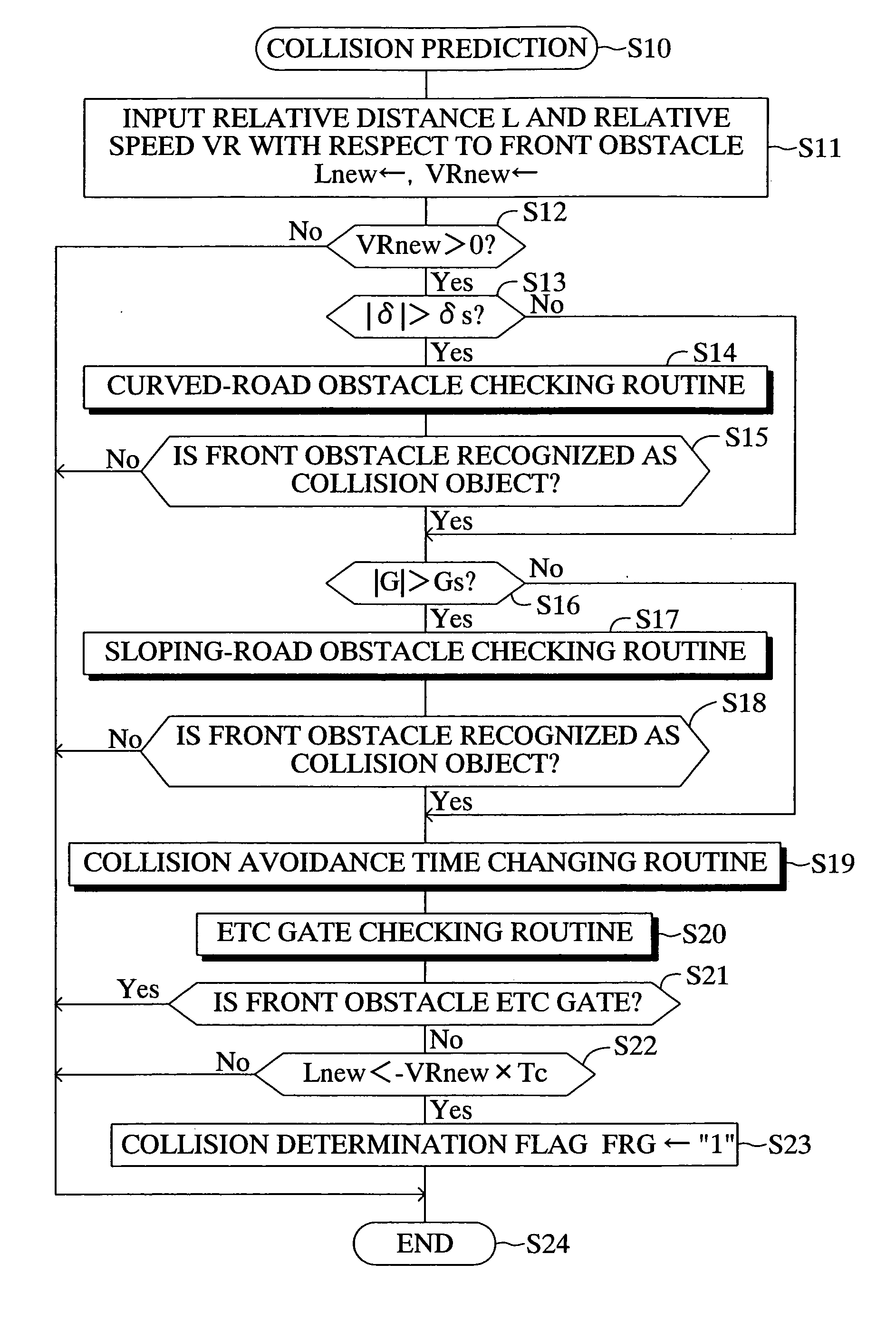
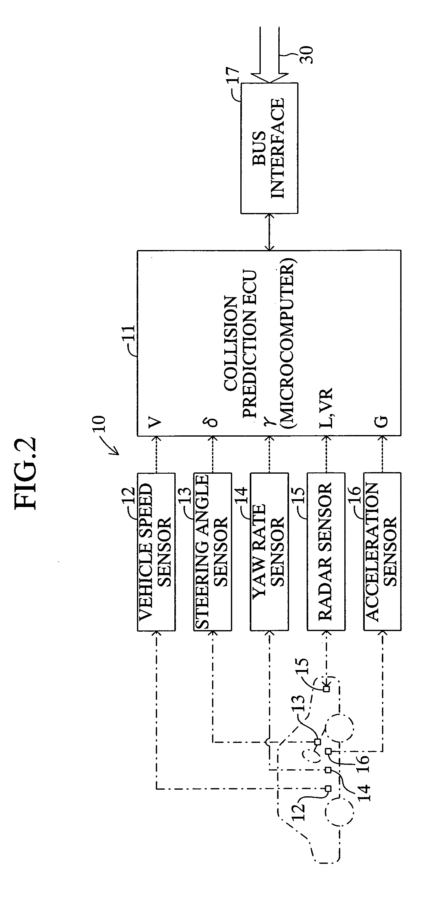
[0116] As can be understood from the above description, the collision prediction ECU 11 of the collision prediction apparatus 10 can accurately estimate the state of presence of a front obstacle; i.e., the radius of curvature R2 of a curve where the front obstacle is present. Further, the collision prediction ECU 11 can check and accurately correct a parameter which indicates the sate of traveling of the vehicle; i.e., acceleration G detected by the acceleration sensor 16. This estimation and correction can be performed on the basis of various types of data supplied from the navigation apparatus 20; i.e., road shape data, road surface condition data, and road gradient data.

[0117] Moreover, the collision prediction ECU 11 can increase the collision avoidance time Tc, which serves as a collision determination reference value, when the vehicle travels on a road section along which a stationary object (the wall of a tunnel, etc.) is disposed or when the vehicle starts traveling from a ...

second embodiment

[0122] As shown in FIG. 9, a navigation apparatus 20 has a communication unit 26, which enables the navigation apparatus 20 to communicate with the outside. The communication unit 26 is connected to the navigation ECU 21, and communicates with the outside at predetermined intervals to thereby acquire the latest travel-related information. Therefore, the communication unit 26 has an antenna 26a for radio communications with the outside. Examples of such latest travel-related information include information regarding traffic congestion and weather near the present location of the vehicle, or traffic accident information reporting that many accidents have occurred along a road on which the vehicle is presently traveling. Other usable examples of communications between the communication unit 26 and the outside include communications between the vehicle and other vehicles (inter-vehicle communications) and communications between the vehicle and roads (road-vehicle communications).

[0123]...


PUM


Abstract

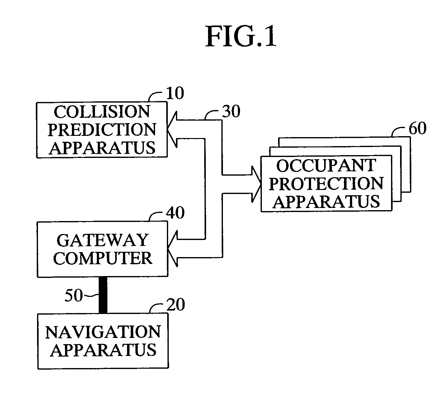
A collision prediction ECU of a collision prediction apparatus estimates a state of presence of a detected front obstacle. At this time, the collision prediction ECU estimates the state of presence on the basis of road shape data supplied from a navigation ECU of a navigation apparatus. Further, the collision prediction ECU checks and corrects the calculated road gradient value. At this time, the collision prediction ECU corrects the gradient value on the basis of road gradient data supplied from the navigation ECU. Further, the collision prediction ECU changes a collision avoidance time on the basis of travel environment data supplied from the navigation ECU. Moreover, the collision prediction ECU obtains an ETC gate pass-through signal from the navigation ECU and determines whether the vehicle is passing through the gate. The collision prediction apparatus performs collation prediction on the basis of the corrected values.

Description

BACKGROUND OF THE INVENTION [0001] 1. Field of the Invention [0002] The present invention relates to a collision prediction apparatus which predictively determines a collision between a vehicle, on which the collision prediction apparatus is mounted, and an obstacle in front of the vehicle along a route of travel (hereinafter simply referred to as a “front obstacle”). [0003] 2. Description of the Related Art [0004] Conventionally, as disclosed in, for example, Japanese Patent Application Laid-Open (kokai) No. 11-263190, there has been known an occupant protection apparatus for a vehicle which operates on the basis of results of determination as to probability of occurrence of a collision. The disclosed collision prediction apparatus acquires predetermined data items, such as position information and vehicle speed information, as information pertaining to the vehicle, and determines the probability of occurrence of a collision of the vehicle on the basis of the predetermined data ite...

Claims


Application Information

Patent Timeline
IPC IPC(8): B60R21/00G01C21/00B60R21/01B60R21/0134B60R21/05B60R21/16B60R22/46G01C21/26G08G1/0969G08G1/16
CPCB60R21/013B60R21/0134G06K9/00805G01C21/3697Y02T10/84G01C21/26G06V20/58B60R21/00
Inventor KAWASAKI, TOMOYA
Owner TOYOTA JIDOSHA KK
Learn More