
Method for monitoring a technical system

a technology of a technical system and a monitoring method, applied in the field of monitoring a technical system, can solve the problems of inability to connect individual control units in any desired way, high cost, error response, etc., and achieve the effect of optimum and simple, cost-effective monitoring and regulation of the overall system

Inactive Publication Date: 2005-02-10
ROBERT BOSCH GMBH
View PDF19 Cites 15 Cited by
  • Summary
  • Abstract
  • Description
  • Claims
  • Application Information

AI Technical Summary

Benefits of technology

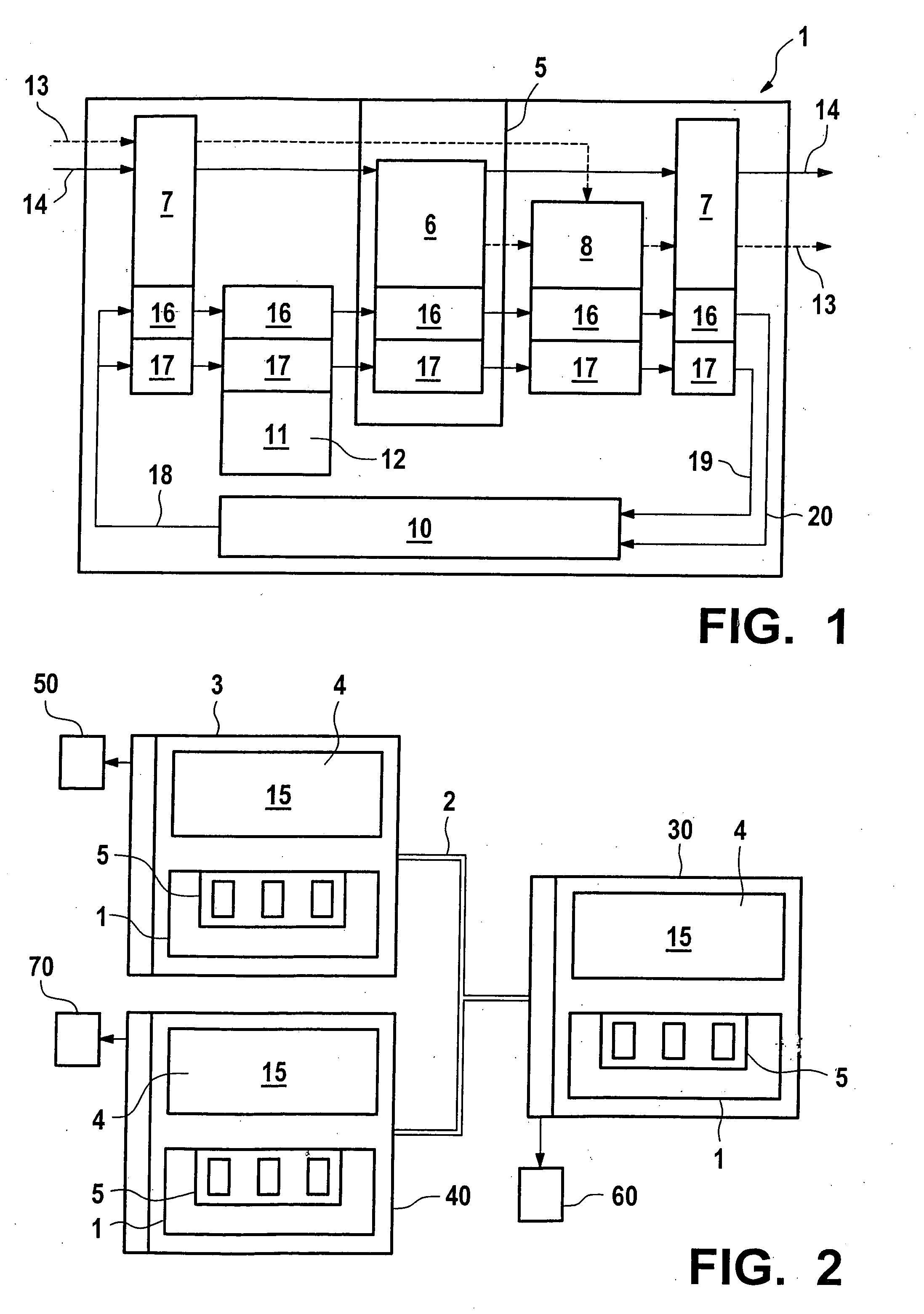
[0009] It is an object of the invention to create a trans-controller monitoring concept to which all control units of a system are connectable to allow optimum, simple, and cost-effective monitoring and regulation of the overall system. Furthermore, the present invention is to make it possible for error recognition and the subsequent error response to take place on different control units.
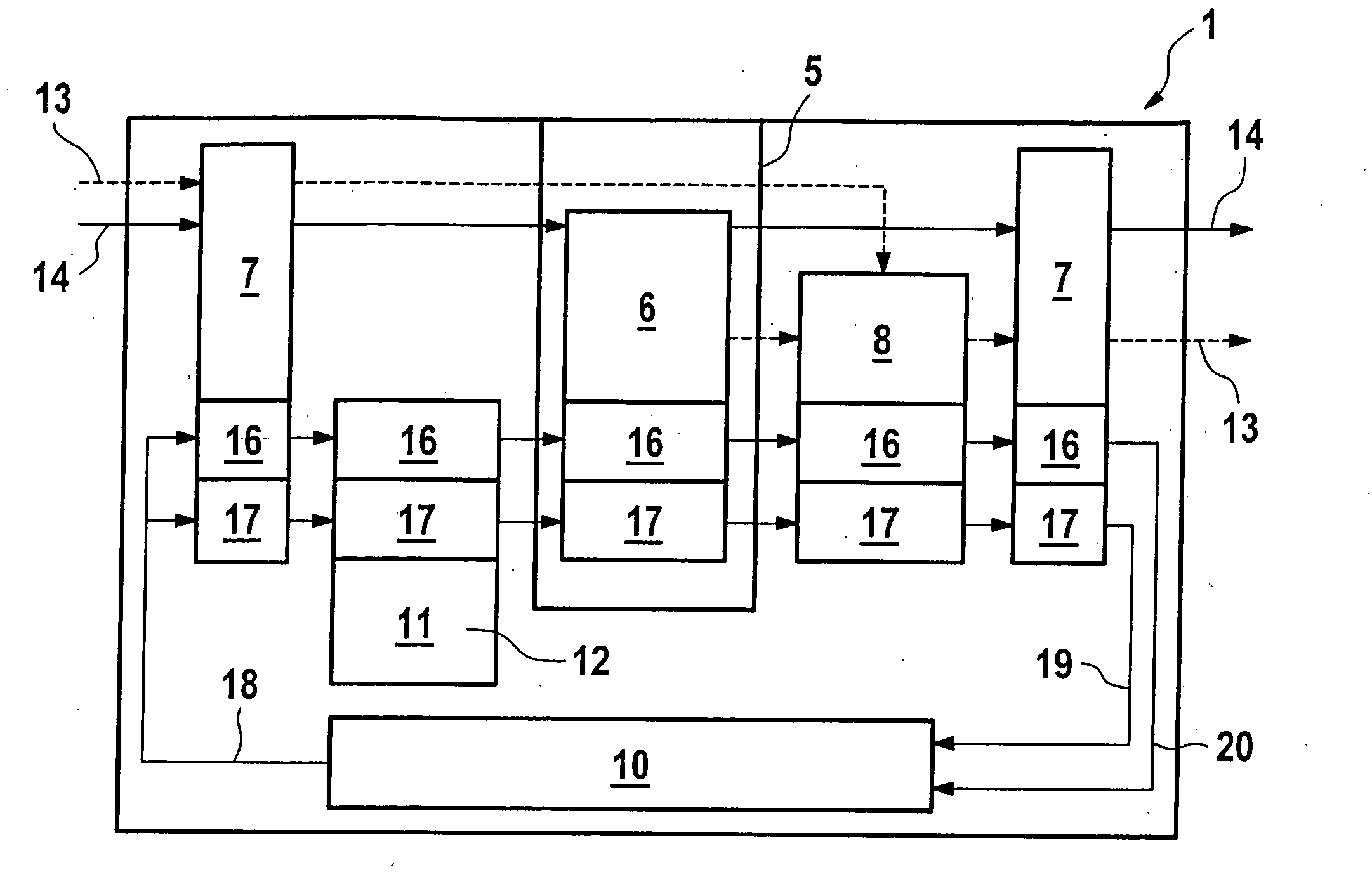
[0010] These and other objects of the invention are achieved by a method for monitoring and / or regulating a technical system, in particular a vehicle, having at least two control units interconnected via a bus system, which have at least one computing element each and which perform monitoring-relevant control procedures and monitoring procedures, wherein a trans-controller software frame, which is implemented in the control units, in particular in the computing elements of the control units, monitors and / or regulates the user software (15) of the control unit. Through the measure according to the present invention to carry out the monitoring and / or the regulation of the user software of the control unit via a trans-controller software frame, which is implemented in the control units, in particular in the computing elements of the control units which perform monitoring-relevant control procedures and monitoring procedures, a monitoring concept is created, to which all control units of a system are connectable. Optimum, simple, and cost-effective monitoring and regulation of the overall system is thus made possible.

Problems solved by technology

This method is known to be intrinsically safe; it is, however, expensive due to the use of two computers.
An error recognized by one control unit results in an error response by the same control unit.
The disadvantage is that the individual control units cannot be connected in any desired way.
This means that it is not possible for an error recognized by a first control unit to result in an error response in another control unit.

Method used


Image

  • Method for monitoring a technical system
  • Method for monitoring a technical system

Examples


Embodiment Construction

[0014] It is advantageous if, after the implementation of the trans-controller software frame, at least two independent levels are provided in the computing element of a control unit, a first level performing the control function and a second level performing the monitoring function. This separation of control function, i.e., user software and monitoring function, makes it possible to design each control unit single-error safe and intrinsically safe. The first level, i.e., performance control of the control unit, is present in all control units. Due to the implementation of the trans-controller software frame, this first level is monitored by a second level, which is a component of the software frame.

[0015] It is furthermore advantageous if a third level of the trans-controller software frame checks the operation of the computing element by monitoring the level which performs the monitoring. The third level is also a component of the software frame and, together with the second lev...


PUM


Abstract

A method for monitoring and / or regulating an technical system, in particular of a vehicle, having at least two control units interconnected via a bus system, which have at least one computing element each and which perform monitoring-relevant control procedures and monitoring procedures, a trans-controller software frame, which is implementable on the control unit, in particular in the computing element of the control unit, which monitors and / or regulates the user software of the control unit.

Description

FIELD OF THE INVENTION [0001] The present invention relates to a method for monitoring a technical system. DESCRIPTION OF RELATED ART [0002] There are different concepts for designing a control unit to be error-free or intrinsically safe. Known ESP / ABS control units in vehicles, for example, currently perform monitoring using the two-computer method, the function software being computed simultaneously on a second, mostly identical computer and the results of both computers being compared. This method is known to be intrinsically safe; it is, however, expensive due to the use of two computers. [0003] A more advantageous option for achieving intrinsic safety of a control unit is monitoring using the three-level method, the second computer being replaced by a more advantageous monitoring module. [0004] German Patent No. 44 38 714 describes a method and a device for controlling a propulsion unit of a vehicle. Here the control unit has only a single computing element, known as a microcom...

Claims


Application Information

Patent Timeline
IPC IPC(8): G05B23/02
CPCG05B19/0428
Inventor SCHWERTFUEHRER, GERIT EDLER VON
Owner ROBERT BOSCH GMBH
Learn More