Padlock

a technology of padlocks and locks, applied in the field of padlocks, can solve the problems of inconvenient one-hand us

Inactive Publication Date: 2005-02-17
YU CHUN TE
View PDF13 Cites 59 Cited by
  • Summary
  • Abstract
  • Description
  • Claims
  • Application Information

AI Technical Summary

Benefits of technology

[0006] It is therefore an objective of the present invention to

Problems solved by technology

It's inconvenient for a one hand person or somebody is

Method used


Image

  • Padlock
  • Padlock
  • Padlock

Examples


first embodiment

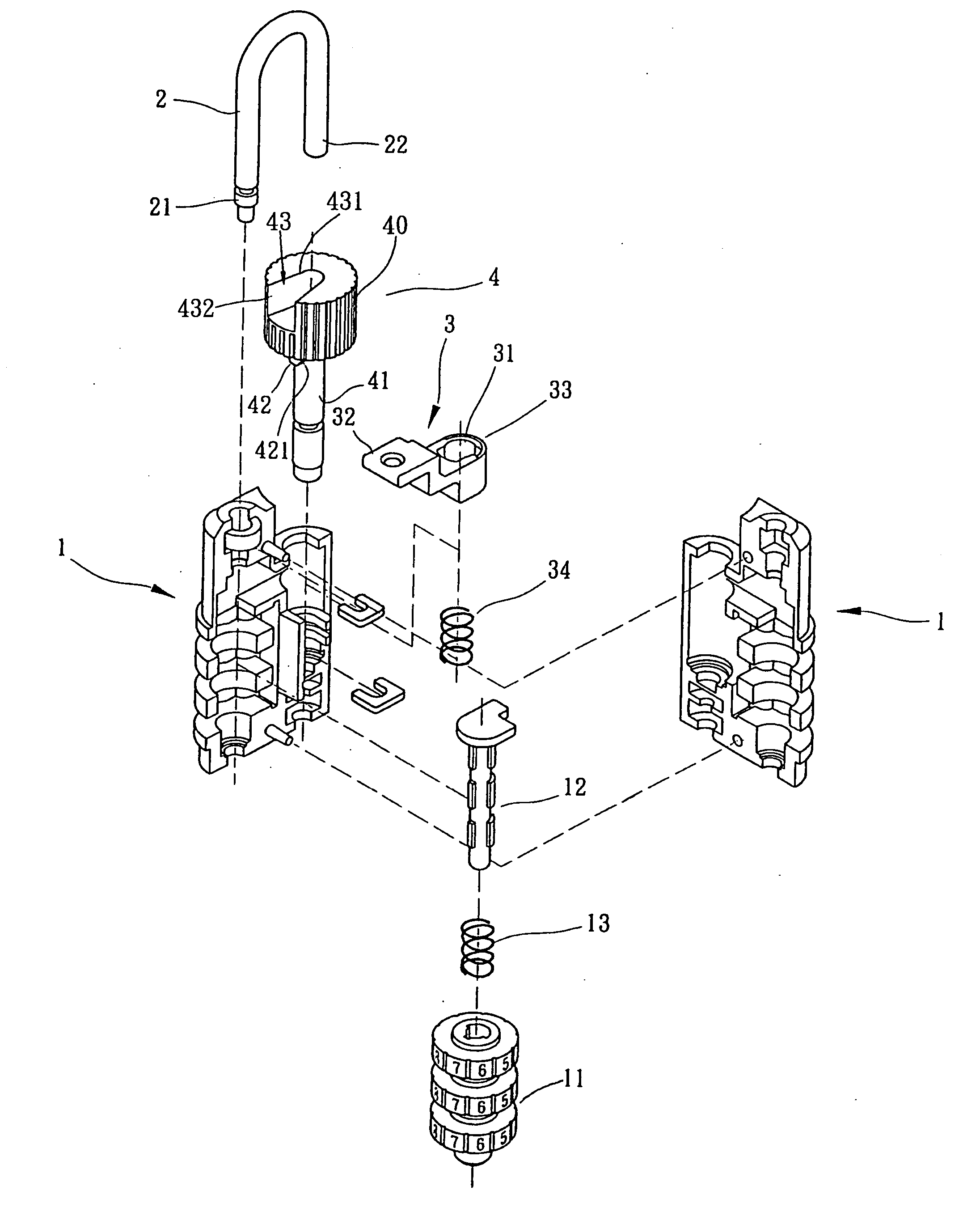
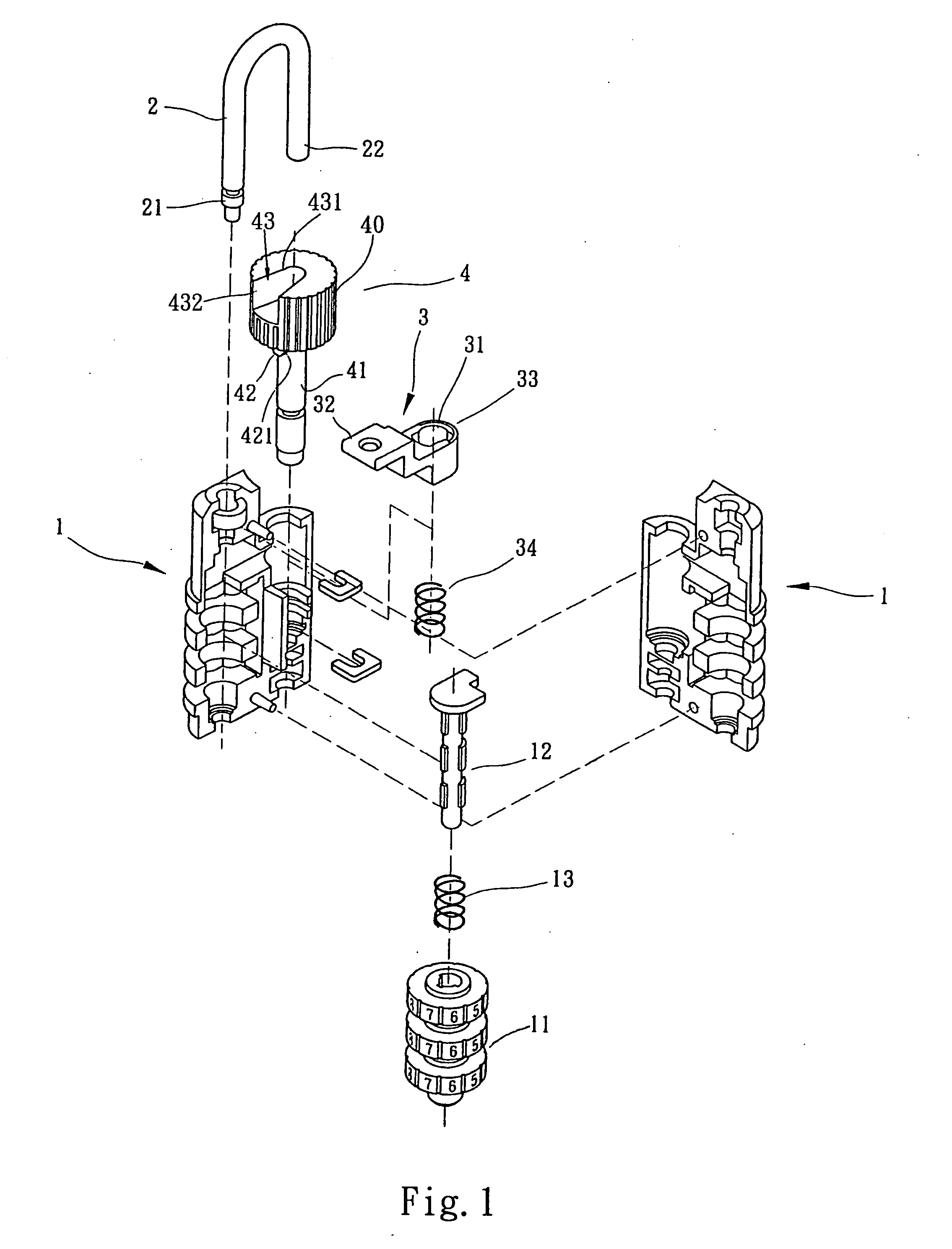
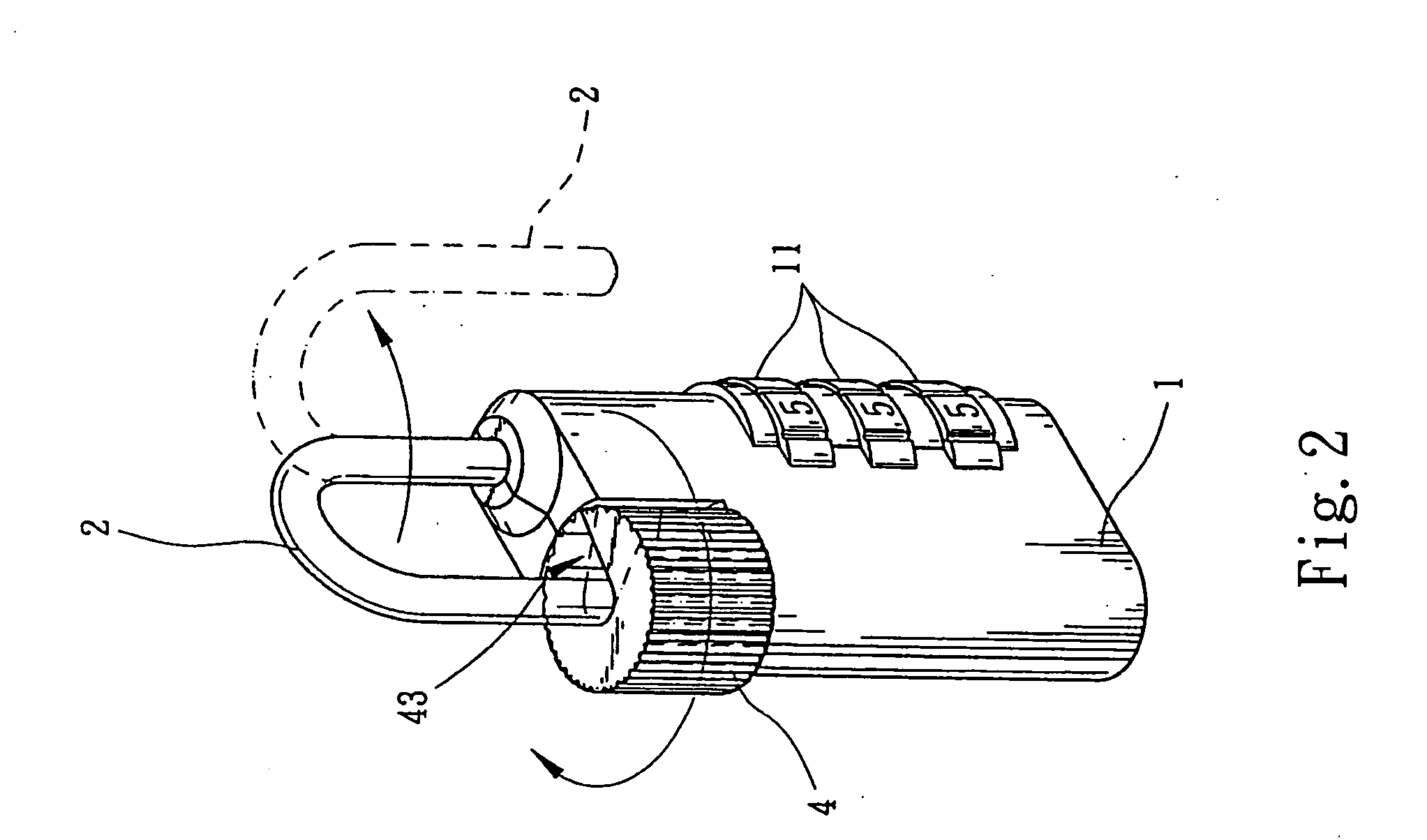
[0030] Please refer to FIG. 1, which shows the present invention. The padlock includes a lock body 1, a shackle 2, a linking member 3 and a restriction device 4. A stem 12 is arranged in the lock body 1. Plural number wheels 11 rotatably mounted around the stem 12. When the number wheels 11 are dialed to the correct number, the stem 12 can be unlocked and moved. A resilient member 13 such as a spring is fitted on the stem 12. The resilient member 13 is compresses between the top end of the stem 12 and the number wheels 11, whereby in normal state, the lock is resiliently forced to abut against the linking member 3. The shackle 2 is substantially U-shaped and has a base end 21 and a free end 22. The base end 21 is pivotally installed in one side of the lock body 1, whereby the shackle 2 can be freely rotated about the base end 21. The linking member 3 is formed with a central through shaft hole 31. The circumference of top side of the shaft hole 31 is formed with a recession 33. Two ...

second embodiment

[0035] With reference to FIG. 5 to FIG. 9, the padlock of the present invention contains a lock body 1b, a shackle 2b, a restriction device 3b, a key operated locking means 4b, a combination locking means 5b and a locking mechanism 6b. A stem 51b of the combination locking means 5b has a recess 53 at top thereof. The recess 53 has a concave 531 at a wall thereof. The restriction device 3b has a restriction button 31b and a driving element 30b. The restriction button 31b is disposed on the lock body 1b and formed with a notch 33b at a top of the restriction button 31b, corresponding to a free end 21b of the shackle 2b. The notch 33b has a gap 33 communicated with a receptacle 32b of the restriction button 31b. The gap 33 has a width larger than the diameter of the free end 21b of the shackle 2b for receiving the same. The driving element30b extended from a bottom of the restriction button 31b has a protrusion 34 thereon for being engaged with the concave 531. The driving element 30b ...

third embodiment

[0036] With reference to FIG. 10 to FIG. 15, the padlock of the present invention mainly contains: a lock body 70, a restriction device 72, a shackle 71, a combination locking means 9 and a key operated locking means 8. The restriction device 72 has a restriction button 722 and a driving element 721. The restriction button 722 is disposed on the lock body 70 and formed with a notch 726. The notch 726 is formed at a top of the restriction button 722 and has a gap 725 communicated with a receptacle 723 of the restriction button 722. The gap 725 has a width larger than the diameter of the free end 712 for receiving the end of the free end 712. The shackle 71 has a base end 711 pivotally installed in the lock body 70 and a free end 712. The combination locking means 9 formed in the lock body 70 for locking or unlocking the base end 711 of the shackle 71. The key operated locking means 8 is formed in the lock body 70 for controlling movements of the restriction device 72 in order the res...


PUM


Abstract

A padlock that can be operated without using both hands is provided. The padlock mainly contains: a lock body, a shackle, a restriction device and a locking means. The shackle has a base end and a free end. The base end is pivotally installed in a side of the lock body whereby the shackle can be freely rotated about the base end without axial movement. The restriction device has a restriction button and a driving element extended from a bottom of the restriction button. The restriction button is disposed on the lock body and is formed with a notch corresponding to the free end of the shackle for restricting the same. The driving element is movably installed in the lock body. The locking means is formed in the lock body for controlling movements of the driving element in order the notch of the restriction button to be engaged with or disengaged from the free end of the shackle, wherein the notch is formed at a top of the restriction button and is extended from a edge to a center of the restriction button.

Description

[0001] This is a continuation-in-part application of the co-pending U.S. Ser. No. 10 / 671,659, application filed on Sep. 29, 2003, and also a continuation-in-part application of the co-pending U.S. Ser. No. 10 / 676,853, application filed on Sep. 30, 2003.TECHNICAL FIELD [0002] This invention relates generally to a padlock, in particular, to provide a padlock having a restriction button formed with a notch for being engaged with a free end of a shackle thereof. BACKGROUND OF THE INVENTION [0003] A conventional padlock contains a lock body, a shackle and a key operated locking means. The shackle has a based end installed in one side of the lock body and a free end. The lock body has concave at the other side thereof. The key operated locking means is for controlling vertical movement of the base end so that the free end of the shackle is engaged with or disengaged from the concave. When the free end of the shackle is engaged with the concave of the lock body, the padlock is locked while...

Claims


Application Information

Patent Timeline
IPC IPC(8): E05B37/00E05B37/02E05B67/10
CPCE05B35/105E05B67/10E05B37/025E05B37/0034Y10T70/424
Inventor YU, CHUN TE
Owner YU CHUN TE
Why Eureka
Try Eureka