Hollow turbine

a technology of hollow turbines and turbines, which is applied in the direction of wind energy generation, wind motors with parallel air flow, hydrogen, etc., can solve the problems of limiting the efficiency of the williams turbine, introducing drag and friction, and failing to disclose what will prevent the turbine from floating away with the curren

Inactive Publication Date: 2005-01-13
FIELDER WILLIAM SHERIDAN
View PDF10 Cites 80 Cited by
  • Summary
  • Abstract
  • Description
  • Claims
  • Application Information

AI Technical Summary

Benefits of technology

[0013] Novel features include: a vacant center axis, since energy is captured at the peripheral surfaces instead of from a central shaft; a debris exhaust hole thats size is application dependent; a lightweight and durable turbine made from composite materials

Problems solved by technology

Another limiting factor of the Williams turbines is the synthetic rubber tires pressed against the outer rim to suspend the turbine as well as transfer rotational energy to an adjacent generator.
The pressing of any rotary connecting element against another introduces drag and friction.
The patents describing the Williams turbines, with the exception of the hydroelectric dam, fail to disclose what will prevent these turbines from floating away with the current.
Both are a potential threat to passing fish that may become entangled within the turbine's blades.
These turbines are also susceptible to passing debris which may also become entangled within the turbine's blades resulting in damage or even catastrophic failure.
The hydro turbine

Method used


Image

  • Hollow turbine
  • Hollow turbine
  • Hollow turbine

Examples


Embodiment Construction

—FIGS.

[0067] The present invention relates generally to hydraulic turbines, and specifically to increasing the efficiency of present designs and to the new applications now possible.

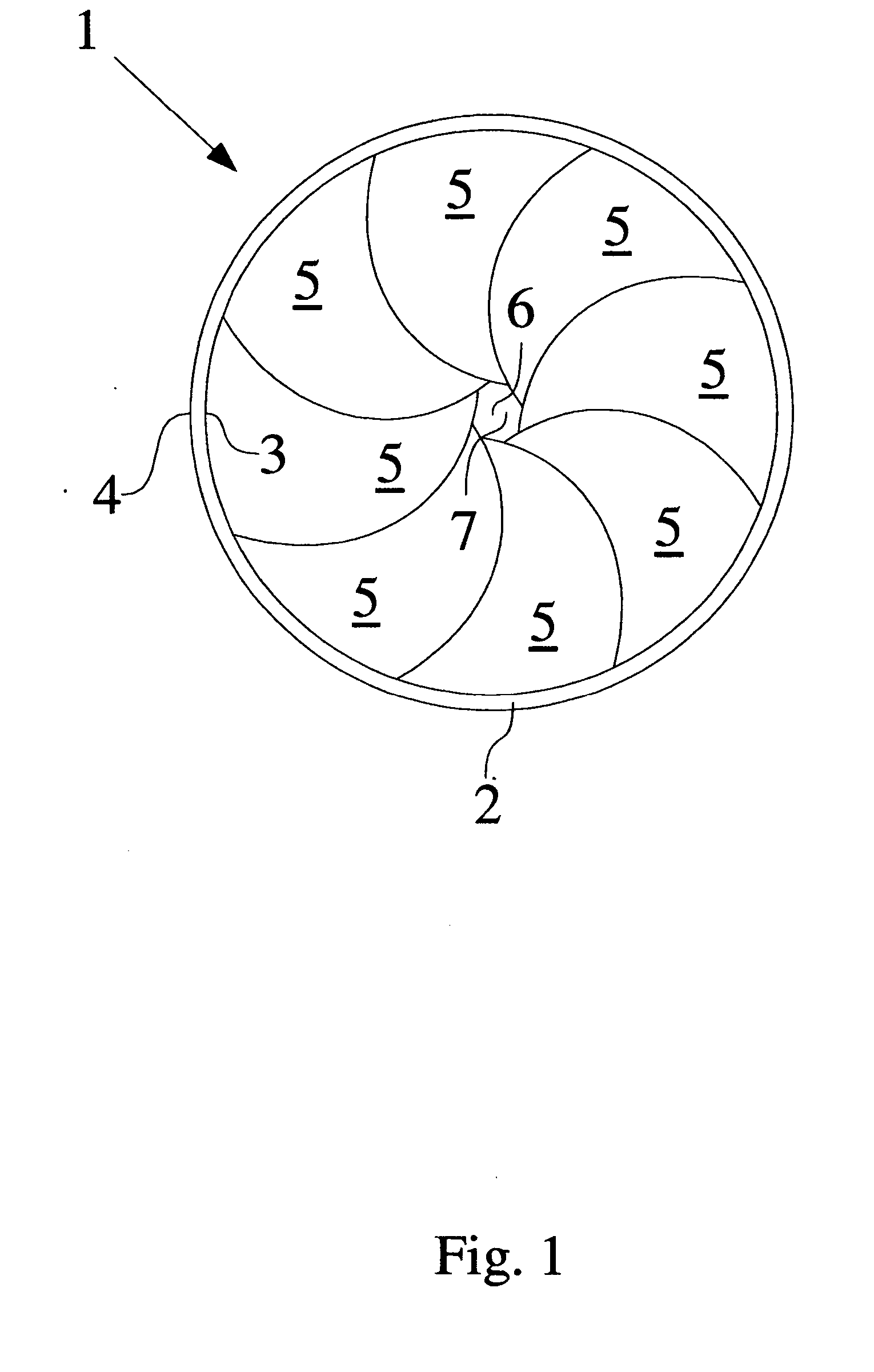
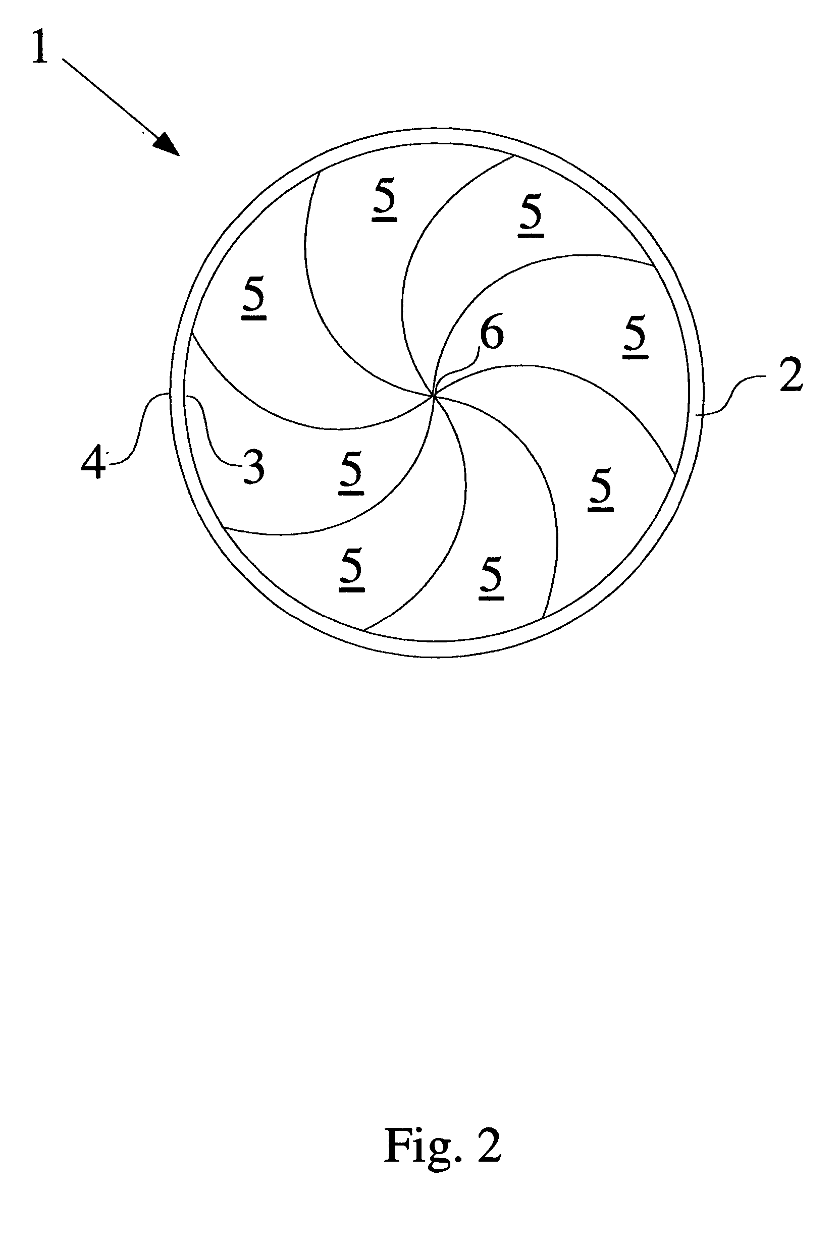
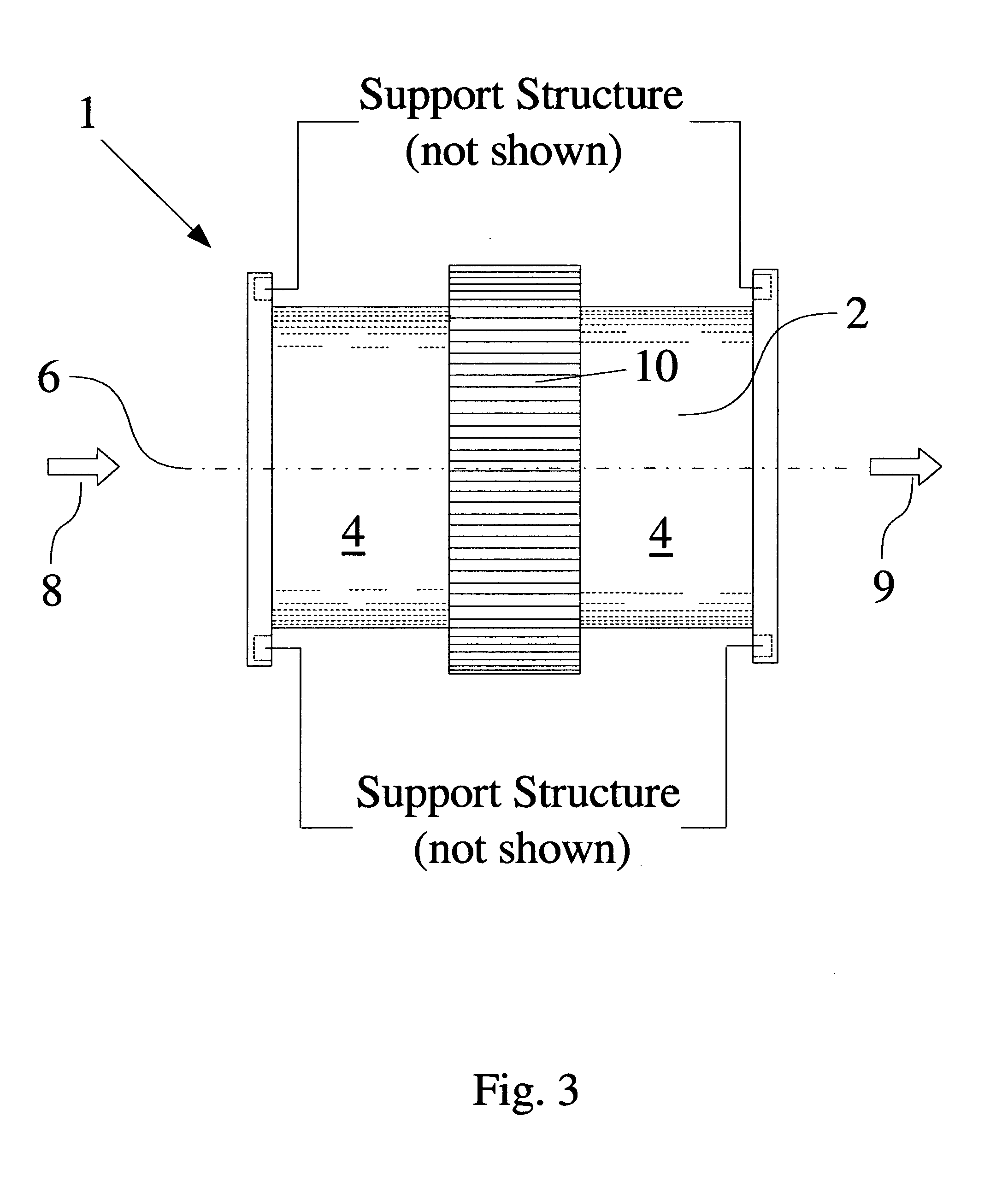
[0068] Referring initially to FIG. 1, as with standard turbines, energy is transferred by the pressure of passing gases or liquids against the turbine's 1 blades 5. Blades 5 are attached to the inner surface 3 of a cylindrical shell 2 which is free to rotate within a support structure 14 as referenced in FIG. 7. This arrangement of blades 5 leaves the center axis 6 of the turbine 1 vacant to allow passing fish and debris to safely exit through. The diameter of this debris exhaust hole 7 is dependent on a balance between the need for efficiency and the need to avoid and or preserve passing fish and debris. Blade design may allow for bidirectional support for tidal applications.

[0069] As best shown in FIGS. 3 and 4, attached to the turbine's outer shell 4 is a rotational energy connecting element 10 to t...


PUM

PropertyMeasurementUnit
Temperatureaaaaaaaaaa
Weightaaaaaaaaaa
Pressureaaaaaaaaaa

Abstract

A versatile turbine suitable for both hydraulic and pneumatic applications. The turbine's blades are affixed to the inner surface of a cylindrical shell which is free to rotate about an outside supporting structure. Rotational energy is transferred from the outer surface of the rotating cylindrical shell, usually by means of a gear; however, there may be applications better suited for a pulley means of transfer. The vacant central axis of rotation can be closed, by incorporating taller blades to achieve a larger surface area, resulting in greater efficiency, or open, by means of shorter blades forming a hole with the distal edges of the blades, to allow for passing fish and or debris to safely exit. The preferred embodiment further includes a means for electricity generation, water purification, and hydrogen production.

Description

CROSS-REFERENCE TO RELATED APPLICATIONS [0001] This application claims benefit of Provisional Application Ser. No. 60 / 485,577 filed Jul. 7, 2003; 60 / 487,372 filed Jul. 15, 2003; 60 / 489,254 filed Jul. 22, 2003; 60 / 494,186 filed Aug. 11, 2003 all by the present inventor.FEDERALLY SPONSORED RESEARCH [0002] Not Applicable. SEQUENCE LISTING OR PROGRAM [0003] Not Applicable. BACKGROUND OF THE INVENTION [0004] 1. Field of Invention [0005] This invention relates generally to turbines and the production of electricity, hydrogen and purified water. [0006] 2. Prior Art [0007] The Hydroelectric Power Plant and Hydroelectric Turbine For Producing Electricity From A Water Current both by Williams are the closest of the prior art found to date. They depict a hydroelectric power plant suitable for applications requiring production of a small amount of electricity. Although there may appear to be similarities between this present invention and the Williams turbines, there are fundamental differences...

Claims


Application Information

Patent Timeline
IPC IPC(8): C02F1/04F01D5/03F03B3/04F03B13/08F03B17/06F03D1/06
CPCC02F1/04C02F1/041C02F2103/08F01D5/03F03B3/04Y02E10/721F03B17/061F03D1/0608Y02E10/22Y02E10/223Y02E10/28F03B13/08Y02E10/20Y02E10/30Y02E10/72Y02P70/50Y02A20/124Y02A20/141Y02A20/144
Inventor FIELDER, WILLIAM SHERIDAN
Owner FIELDER WILLIAM SHERIDAN
Why Eureka
Try Eureka