
Sheet conveying apparatus and image forming apparatus

a conveying apparatus and sheet technology, applied in the field of sheet conveying apparatus, can solve the problems of large apparatus, abnormal sound, and the end of the capability of skew conveying correction

Inactive Publication Date: 2005-02-17
CANON KK
View PDF4 Cites 43 Cited by
  • Summary
  • Abstract
  • Description
  • Claims
  • Application Information

AI Technical Summary

Benefits of technology

[0017] Hence, the present invention has been made in view of the above-described situation, and the object of the invention is to provide a sheet conveying apparatus and an image forming apparatus, which can correct the skew conveying of a sheet without allowing the tugging of the sheet to occur.

Problems solved by technology

However, in such a loop registration system, a loop space for forming a loop has been certainly required, thereby making the apparatus large-sized.
Further, when the loop space is not sufficiently secured, there is a problem in that a jam (sheet jam) due to a buckling particularly in the sheet such as a thin paper being weak in rigidity has occurred, and abnormal sound (so-called loop sound) has been emitted when the sheet was abutted against the registration roller pair.
Furthermore, there is a problem in that a skew conveying correction capability ends up being changed depending on strength of the sheet rigidity.
To be more specific, in the case of the thin paper, which is weak in rigidity, the leading edge of the sheet lacks an abutting force when abutting against the registration roller nip, and there are some cases where the leading edge of the sheet does not sufficiently abut against the registration roller pair, and in this case, it is totally impossible to perform the skew conveying correction.
Further, in the case of a thick paper and the like which is strong in rigidity, there is a problem in that the sheet ends up going through the nip of the registration roller pair due to an impact caused by abutting against the nip of the registration roller.
To prevent this from occurring, for example, when an attempt is made to give a load and the like to the registration roller pair by a brake member, it invites a cost-up of the product.
Still further, when there is a curl or a crease on the leading edge of the sheet, the leading edge of the sheet is unable to precisely run along the nip portion of the registration roller, and as a result, there arises a problem in that a precise correction of the skew conveying cannot be performed, thereby lowering a print accuracy.

Method used


Image

  • Sheet conveying apparatus and image forming apparatus
  • Sheet conveying apparatus and image forming apparatus
  • Sheet conveying apparatus and image forming apparatus

Examples


first embodiment

[0048] (First Embodiment)

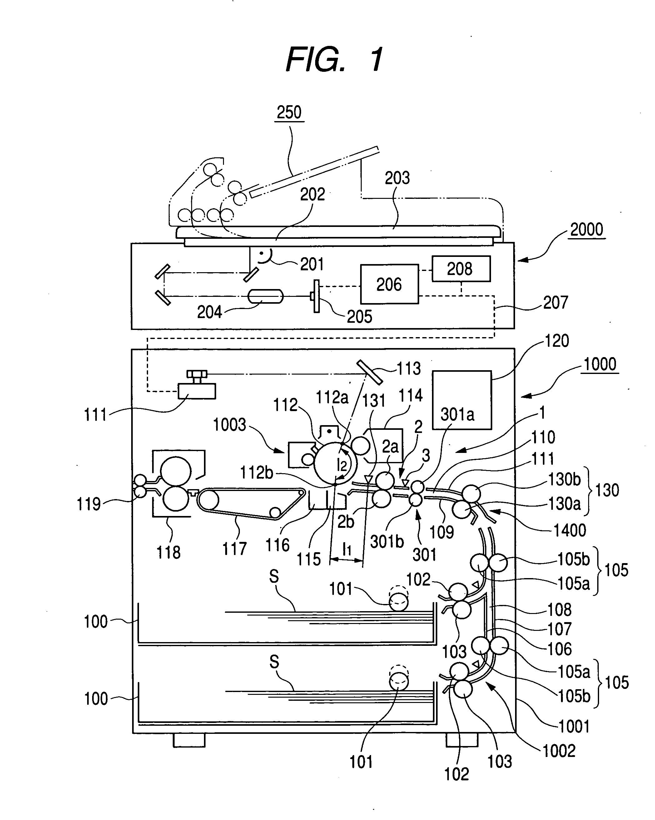
[0049]FIG. 1 is a sectional view of a printer, which is one example of an image forming apparatus comprising a sheet conveying apparatus according to a first embodiment of the present invention.

[0050] In the drawing, reference numeral 1000 denotes a printer, and the printer 1000 comprises a printer body 1001 and a scanner 2000 arranged on the top surface of the printer body 1001.

[0051] Here, the scanner 2000 for reading an original comprises a scanning optical light source 201, a platen glass 202, an open-close original thick plate 203, a lens 204, a photodiode (photoelectric conversion) 205, an image processing portion 206, a memory portion 208 for storing an image processing signal processed at the image processing portion 206, and the like.

[0052] When reading the original, an illustrated original placed on the platen glass 202 is irradiated with light by the scanning optical light source 201 so as to be read. The read original image is processed by the...

second embodiment

[0095] (Second Embodiment)

[0096] Next, a second embodiment of the present invention will be described.

[0097]FIG. 9 is a flowchart showing a skew conveying correction operation of a sheet conveying apparatus according to the present embodiment, and a sheet skew conveying correction according to the present embodiment will be described with reference to the same drawing.

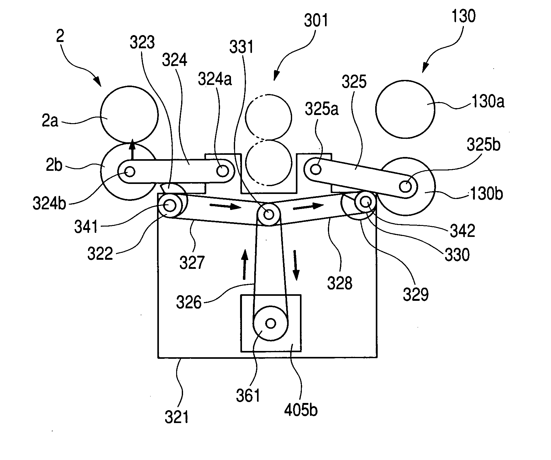
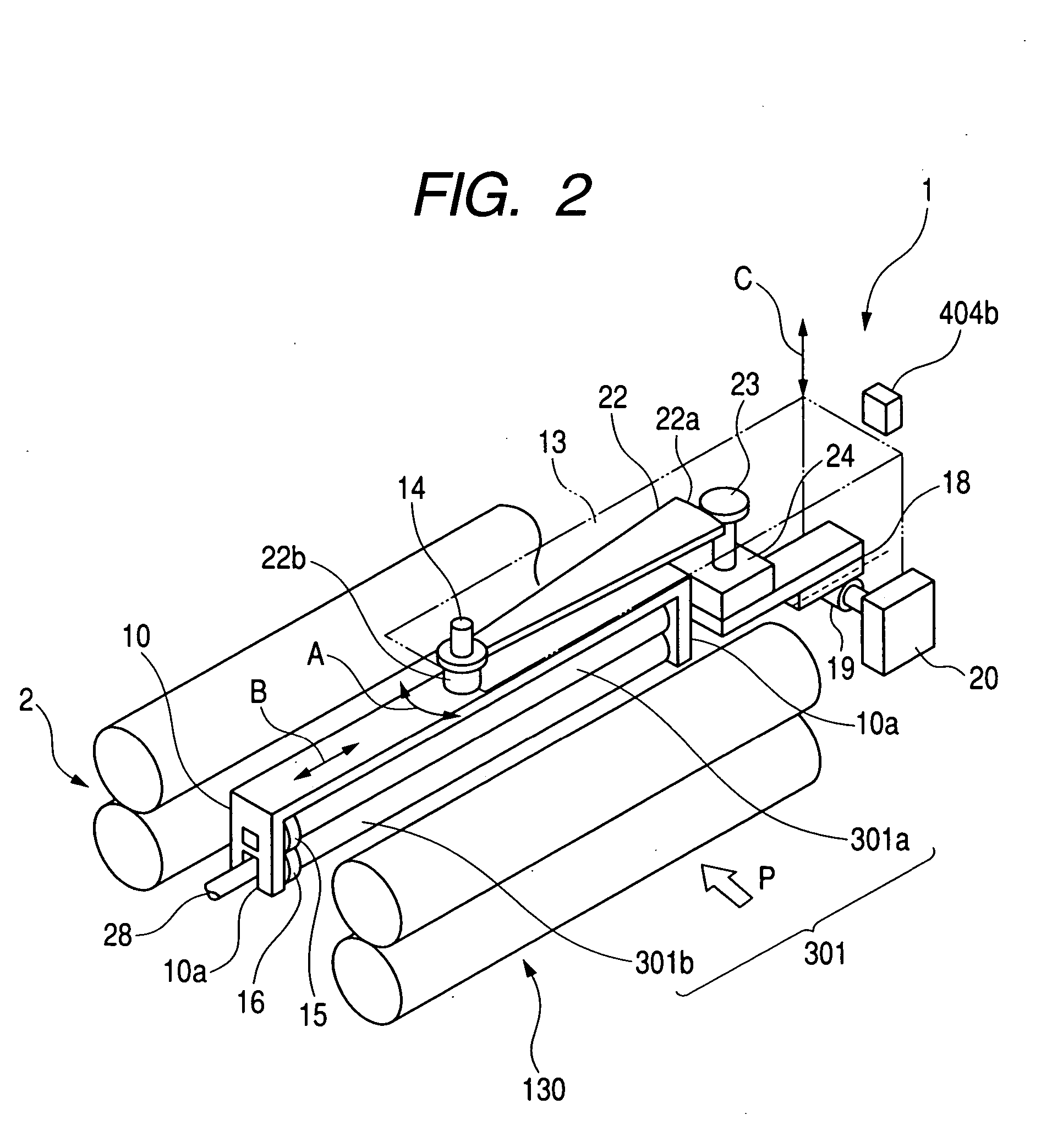
[0098] First, when an unillustrated start button of a printer 1000 is pushed, a lateral moving motor 20 and a swing motor 24 are driven, and by an unillustrated home position sensor, the initializing operation of the swing direction of a correction-roller pair 301 and the position in a thrust direction is performed (Step 1).

[0099] Accompanied with this initializing operation, a motor 404b is driven, and an upper correction roller 301a is lifted so as to separate from a lower correction roller 301b. Further, a press-contacting / separating motor 405b is driven so that a downstream roller pair 2 and a upstream roller pa...

third embodiment

[0107] (Third Embodiment)

[0108] Next, a third embodiment of the present invention will be described.

[0109]FIG. 12 is a flowchart showing a skew conveying correction operation of a sheet conveying apparatus according to the present embodiment, and the skew conveying correction of a sheet according to the present embodiment will be described with reference to the drawing.

[0110] First, when an unillustrated start button of a printer 1000 is pushed, a lateral moving motor 20 and a swing motor 24 are driven, and by an unillustrated home position sensor, the initializing operation of the swing direction of a correction roller pair 301 and the position in a thrust direction is performed (Step 1).

[0111] Accompanied with this initializing operation, a motor 404b is driven, and an upper correction roller 301a is lifted so as to separate from a lower correction roller 301b. Further, a press-contacting / separating motor 405b is driven so that a downstream roller pair 2 and a upstream roller p...


PUM


Abstract

The object of the present invention is to provide a sheet conveying apparatus capable of correcting the skew conveying of a sheet without causing a tugging. In order to accomplish the object, the sheet conveying apparatus includes a detection unit for detecting an inclination to a sheet conveying direction of a sheet to be conveyed; an inclination correction unit for correcting the inclination of the sheet by rotating in a state of nipping the sheet of an inclined state based on a detection signal from the detection unit; a first conveying unit, which is provided in the upstream side of the inclination correction unit and nips the sheet toward the inclination correction unit and conveys the same; a first nipping release unit for releasing a nipping state of the second sheet conveying unit, which is provided in the downstream side of the inclination correction unit and nips the sheet from the inclination correction unit and convey the same to the downstream side; a second nipping release unit for releasing the nipping state of the second sheet conveying unit; and a control unit for controlling the first nipping release unit and the second nipping release unit to selectively release the sheet nipping state of the first sheet conveying unit and the second sheet conveying unit according to an inclination correction operation by the inclination correction unit.

Description

[0001] This application claims priority from Japanese Patent Application No. 2003-198786 filed Jul. 17, 2003, which is hereby incorporated by reference. BACKGROUND OF THE INVENTION [0002] 1. Field of the Invention [0003] The present invention relates to a sheet conveying apparatus provided in an image forming apparatus, and more in particular, it relates to a constitution for correcting inclination (or skew) of the sheet to be conveyed. [0004] 2. Related Background Art [0005] Conventionally, in general, an image forming apparatus and an image reading apparatus such as a copying machine, a printer, a facsimile, a scanner and the like comprise a sheet conveying apparatus for conveying a sheet such as a recording paper and an original to an image forming portion and an image reading portion. This sheet conveying apparatus is sometimes provided with correction means for performing a skew conveying correction of the sheet and a positional deviation correction of the sheet to align the at...

Claims


Application Information

Patent Timeline
IPC IPC(8): B65H9/00B65H5/06B65H9/16B65H9/12
CPCB65H9/002B65H2404/14B65H2404/14212B65H2404/1442B65H2511/216B65H2220/09B65H2511/242B65H2220/02B65H2220/11B65H2220/01B65H2511/24
Inventor HASHIMOTO, TATSUAKI
Owner CANON KK
Features
  • Generate Ideas
  • Intellectual Property
  • Life Sciences
  • Materials
  • Tech Scout
  • Unparalleled Data Quality
  • Higher Quality Content
  • 60% Fewer Hallucinations
Learn More