Ambient light controlled display and method of operation

Inactive Publication Date: 2005-02-17
MOTOROLA INC
View PDF11 Cites 127 Cited by
  • Summary
  • Abstract
  • Description
  • Claims
  • Application Information

AI Technical Summary

Problems solved by technology

In places where the ambient light level is low, the information displayed on the display of a portable device, particular if it includes small high resolution icons, or text, may be difficult to read.
However, under intermediate light level c

Method used


Image

  • Ambient light controlled display and method of operation
  • Ambient light controlled display and method of operation
  • Ambient light controlled display and method of operation

Examples


first embodiment

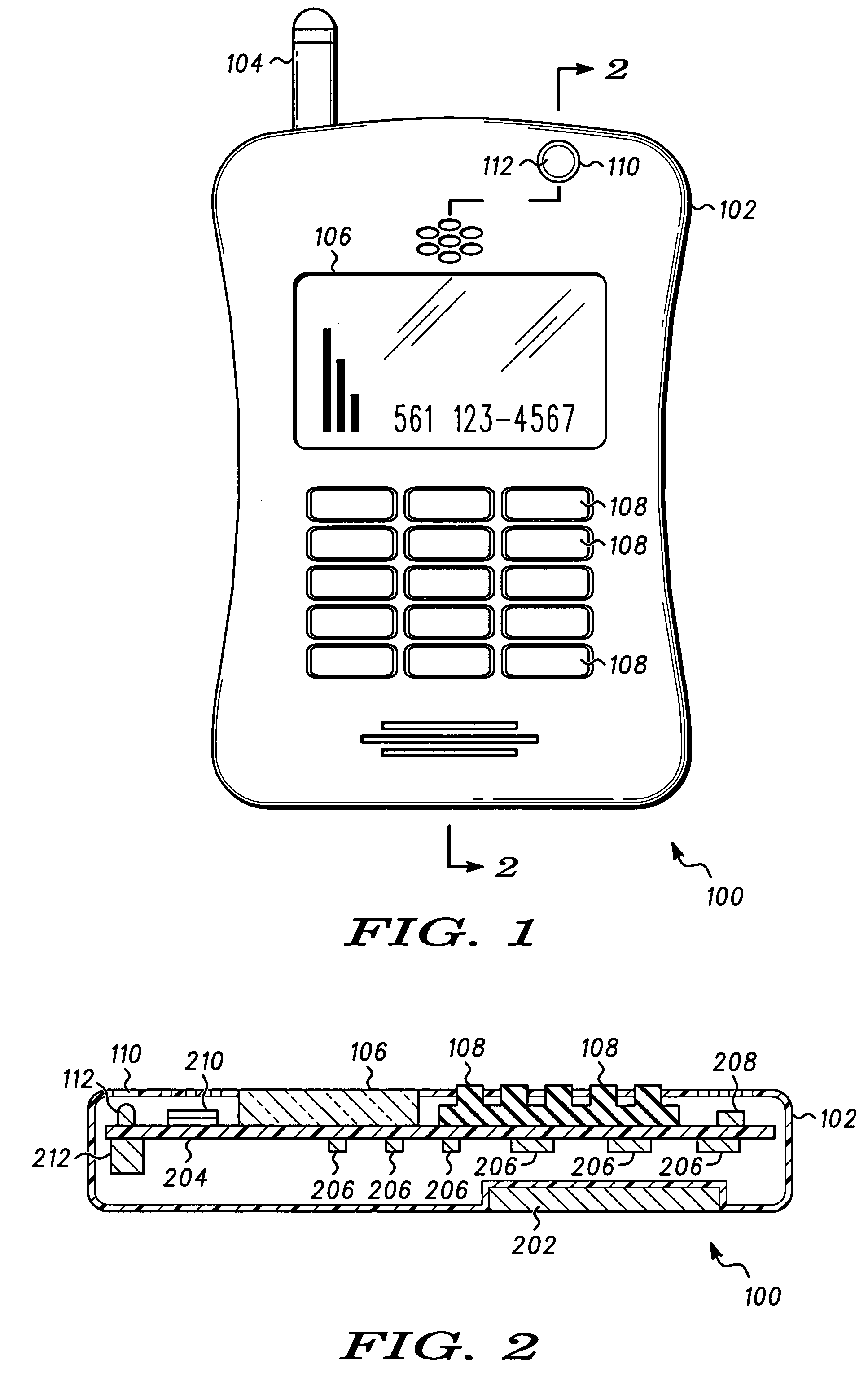
[0018]FIG. 1 is a front view of a wireless communication device 100 and FIG. 2 is a cross sectional side view of the wireless communication device shown in FIG. 1. The wireless communication device 100 comprises a housing 102 that mechanically couples and supports a plurality of components including an antenna 104, a keypad 108, and a battery 202. The housing 102 encloses a circuit board 204 that supports and electrically interconnects the keypad 108, a plurality of electrical circuit components 206 that are part of one or more electrical circuits of the wireless communication device 100, a display 106, a microphone 208, a speaker 210, and an incoming communication alert 212.

[0019] The housing 102 also includes an ambient light sensor window 110. An ambient light sensor 112 is connected to, and supported on the circuit board 204 in alignment with the light sensor window 110. The light sensor 112 is used to measure ambient light levels, and the display 106 is operated according to t...

second embodiment

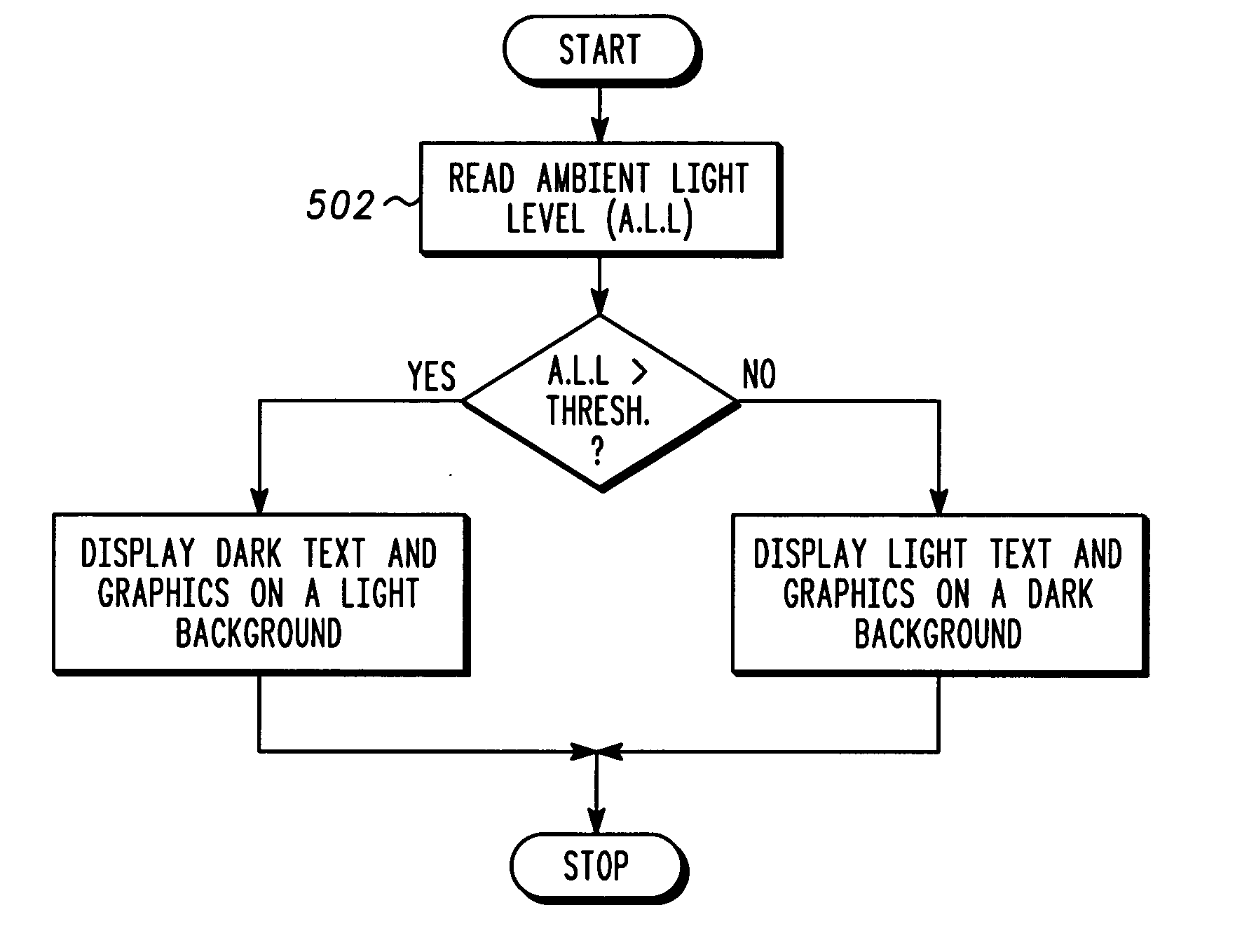
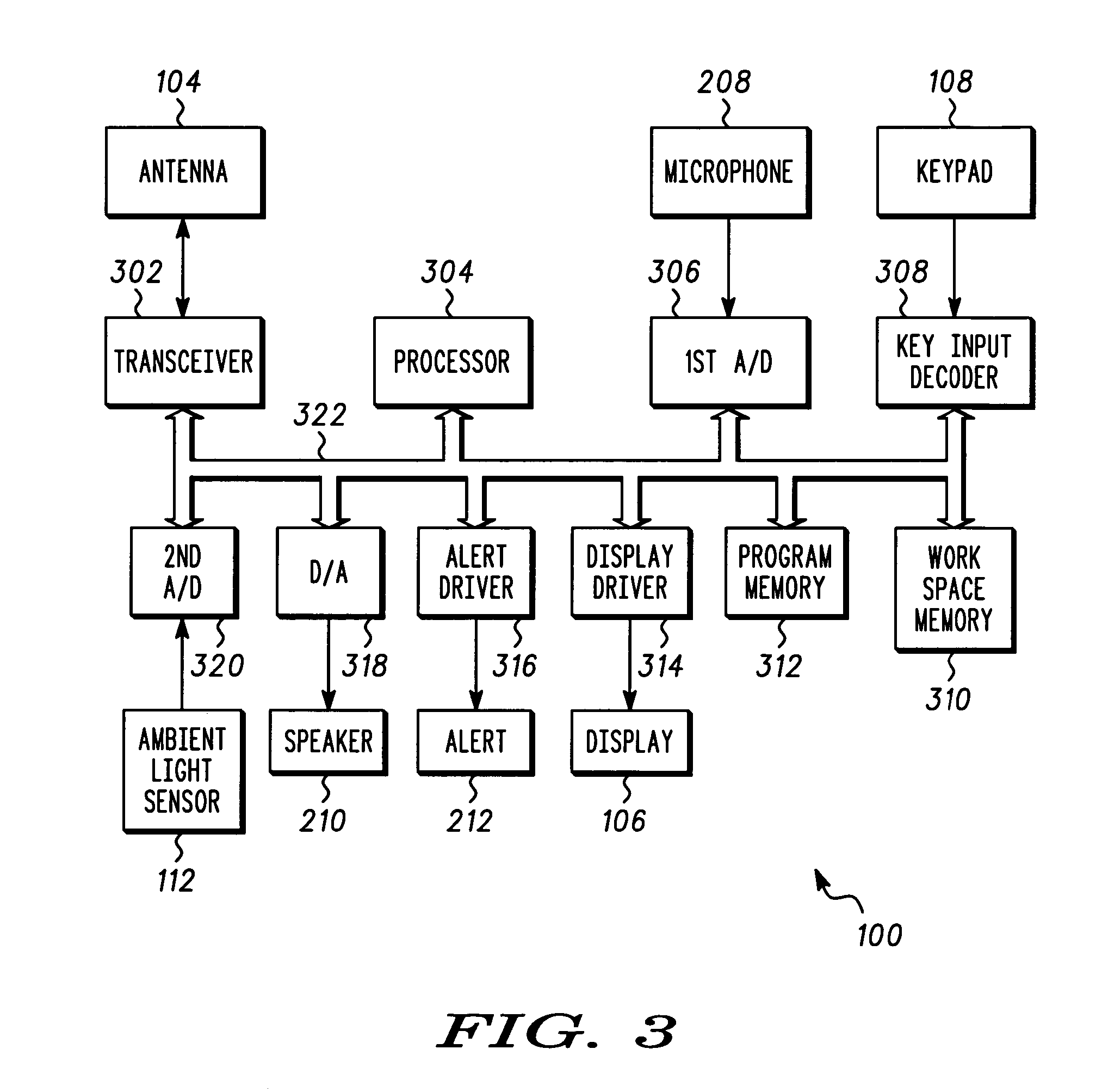
[0035]FIG. 5 is a flow chart of a method of operating the wireless communication device 100 shown in FIGS. 1-3 according to the invention. A program embodying the method shown in FIG. 5 can be stored in the program memory 312, and executed by the processor 304. In block 502, the A.L.L. is read, e.g., by the processor 208 through the signal bus 322, and second A / D 320 from the ambient light sensor 112. Thereafter, in decision block 504, the A.L.L. is compared to a threshold. If it is determined in block that the A.L.L. exceeds the threshold, the method continues with block 506 in which dark text and graphics are displayed on a light background. If on the other hand it is determined in block 504 that the A.L.L. does not exceed the threshold, then in block 508 light text and graphics are displayed on a dark background.

[0036] Thus, under low light conditions the method shown in FIG. 5 displays light text and graphics on a dark background in order to improve readability, and reduce eye s...

third embodiment

[0038]FIG. 7 is a flow chart of a method of operating the wireless communication device shown in FIGS. 1-3 according to the invention. A program embodying the method shown in FIG. 7 can be stored in the program memory 312, and executed by the processor 304. In block 702 the ambient light level (A.L.L.) is read, e.g., by the processor 208 through the signal bus 322, and second A / D 320 from the ambient light sensor 112. Block 704 is a decision block the outcome of which depends on whether the A.L.L exceeds a first threshold value (labeled THRESH—1 in FIG. 7). If so then in block 706 indicia color variable that determines the color of one or more indicia (e.g., icons, text) displayed on the display 106 is set to a first predetermined color, and in block 708 a background color variable, that determines the color of a background displayed on the display 106 is set to a second predetermine value. The first and second predetermined values can be chosen by experimenting with human subjects ...


PUM


Abstract

A portable electronic apparatus (100) includes a ambient light sensor (112) for measuring ambient light levels, a display (106) for displaying text and icons, on a background, and a processor (304) coupled to the display (106), and the light sensor for causing indicia to be displayed on the display (106), and adjusting the color and/or size characteristics of the indicia and/or background according to the ambient light level measured through the ambient light sensor (112)

Description

BACKGROUND OF THE INVENTION [0001] 1. Field of the Invention [0002] The present invention relates in general to displays. More particularly, the present invention relates to displays for portable devices. [0003] 2. Description of Related Art [0004] Portable electronic devices that include displays such as cellular telephones, portable digital assistants (PDA), and portable game consoles are widely used. Recently, devices having larger and higher resolution displays that are capable of displaying images with higher color fidelity have been introduced. Such displays generally allow for improved user interfaces. [0005] Such portable electronic device, are carried with their users indoors and outdoors, and operated under a wide variety of ambient light conditions. In places where the ambient light level is low, the information displayed on the display of a portable device, particular if it includes small high resolution icons, or text, may be difficult to read. One approach to increasin...

Claims


Application Information

Patent Timeline
IPC IPC(8): G09G5/02H04M1/22H04M1/724
CPCG09G5/02G09G2320/0626G09G2330/021H04M2250/12H04M1/22H04M1/72519G09G2360/144H04M1/724
Inventor BESHARAT, MOHAMMADHAIDAR, FAISAL A.
Owner MOTOROLA INC
Why Eureka
Try Eureka