Dry ice drinking vessel

a drinking vessel and dry ice technology, applied in the field of dry ice drinking vessels, can solve the problems of only practicality, prior art devices do not serve to create visual effects, and dry ice can be dangerous to touch, so as to prolong the time between preparing and serving beverages, enhance visual effects, and improve the usefulness of drinking vessels

Inactive Publication Date: 2005-02-24
NIELSEN PETER
View PDF7 Cites 13 Cited by
  • Summary
  • Abstract
  • Description
  • Claims
  • Application Information

AI Technical Summary

Benefits of technology

[0007] The boiling, smoking visual effect of the submerged dry ice renders a beverage visually attractive. The visual effect is enhanced by lighting the drinking vessel from below, as by upward-shining light-emitting diodes installed in a tray for serving beverages. The chilling effect of the dry ice also adds to the appeal of beverages served using the drinking vessel.
[0008] The usefulness of the drinking vessel is improved and the time between preparing and serving the beverage may be extended by providing a removable cap blinding the perforations of the partition. The removable cap substantially prevents the beverage from flowing through the perforations to the dry ice. The removable cap has a tab extending above the level of the beverage, allowing a server to pull the tab and thereby remove the cap from the perforations, allowing the beverage to flow through the perforations to the dry ice. The use of the removable cap allows a server to charge the drinking vessel with dry ice and pour the beverage into the drinking vessel up to an hour before serving the beverage.

Problems solved by technology

Dry ice can be dangerous to touch, but is commonly used in shipping perishable items.
Prior art dispenser devices such as the Switzer and Eager devices filled a need for cool beverages but were only practical where a beverage was to be served to a large number of people from a single dispenser.
The prior art devices do not serve to create a visual effect.

Method used


Image

  • Dry ice drinking vessel
  • Dry ice drinking vessel
  • Dry ice drinking vessel

Examples


first embodiment

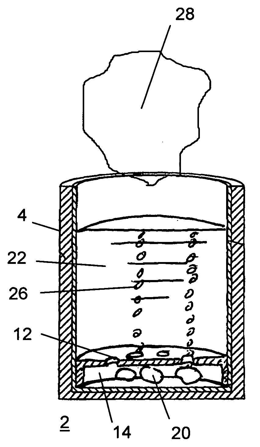
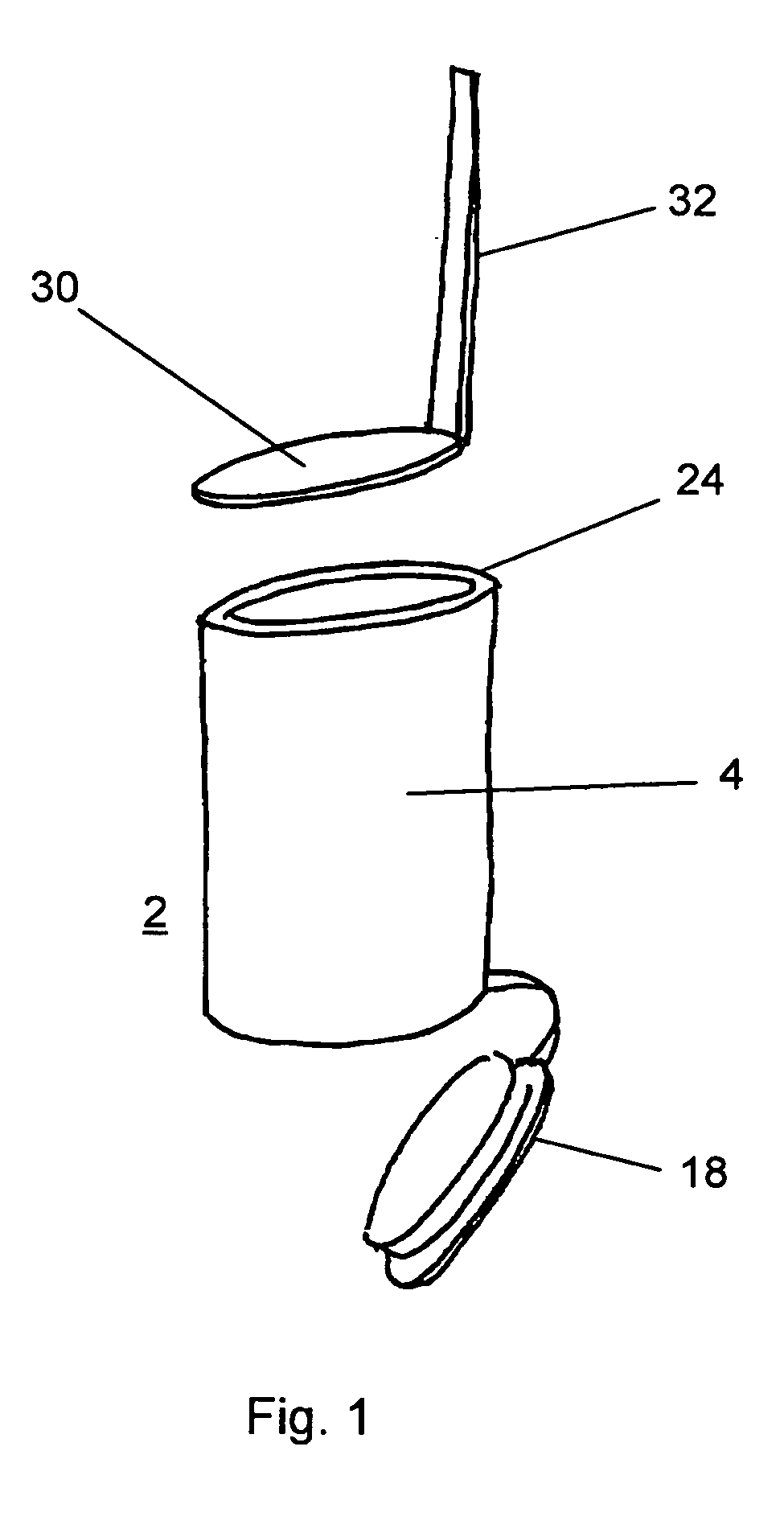
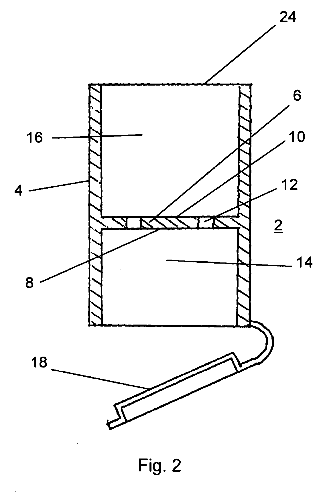
[0022] The Invention is in the form of a small drinking vessel such as might be used to consume alcoholic “shots.” the Invention is illustrated by FIGS. 1-4. A generally cylindrical drinking vessel 2 has a vessel wall 4. As shown by FIGS. 2-4, the drinking vessel 2 has a partition 6 in fixed engagement with the vessel wall 4. Partition 6 has a first side 8 and a second side 10. At least one perforation 12 through the partition 6 communicates between first side 8 and second side 10. Partition 6 and wall 4 together define a first interior volume 14 and a second interior volume 16. Partition 6 segregates first interior volume 14 from second interior volume 16, while allowing fluid and pneumatic communication between first interior volume 14 and second interior volume 16.

[0023] Drinking vessel 2 has a bottom 18 selectable engaging the wall 4. Bottom 18 has an open position illustrated by FIGS. 1 and 2, and a closed position illustrated by FIGS. 3 and 4. In the open position, dry ice pel...

second embodiment

[0027]FIGS. 5 and 6 illustrate the drinking vessel 2. Partition 6 is in fixed engagement with wall 4. Bottom 18 and partition 6 cooperate to define first interior volume 14. Bottom 18 selectably engages wall 4 in a fluid-tight connection using any suitable engagement means, such as a snap connection or threads 34. Dry ice 20 is placed within first interior volume 14 and beverage 22 is poured through open rim 24. Beverage flows through perforations 12 but does not leak from the vessel 2 because of the fluid tight connection between wall 4 and bottom 18. Dry ice 20 sublimates, causing the boiling, smoking effect and chilling beverage 22.

third embodiment

[0028]FIGS. 7-10 illustrate a In the embodiment of FIGS. 7-10, bottom 18 is in fixed engagement with wall 4 and partition 6 selectably engages wall 4. Partition 6 is inserted into the drinking vessel 2 through open rim 24. Partition 6 slidably engages wall 4, securing partition 6 in place within drinking vessel 2 and confining dry ice 20 within the first interior volume 14.

[0029] In the third embodiment illustrated by FIGS. 7-9, the partition 6 has perforations 12. In the variation on the third embodiment illustrated by FIG. 10, partition has no perforations 12 and instead the diameter of partition 6 is less than the inside diameter of wall 4 of drinking vessel 2. The resulting space between the wall 4 and the partition 6 allows the beverage 22 to flow around partition 6 to reach dry ice and allows bubbles 26 of carbon dioxide to flow from dry ice 20. Spring members 36 resiliently engage wall 4, holding partition 6 in place within the drinking vessel 2.


PUM


Abstract

The Invention is an apparatus which may be a drinking vessel to contain dry ice submerged within a beverage to create a visual effect. A partition has a first side and a second side and is adapted to contain dry ice on the first side. The partition is adapted to allow the beverage to flow from the second side of said partition to said first side of said partition when said partition is immersed in the beverage, exposing the beverage to the dry ice, creating a visual effect and chilling the beverage.

Description

RELATED APPLICATIONS [0001] This application claims priority from U.S. provisional patent application No. 60 / 405,468 filed Aug. 22, 2002 and U.S. utility patent application No. 10 / 645,019, filed Aug. 21, 2003, the disclosures of which are hereby incorporated by reference.BACKGROUND OF THE INVENTION [0002] Dry ice is frozen carbon dioxide. When placed in a liquid that is at room temperature, the carbon dioxide absorbs heat from the liquid and undergoes a change of state, sublimating to carbon dioxide gas. The carbon dioxide gas bubbles through the liquid, chilling the air above the liquid. Water vapor in the air condenses, causing a vapor or fog to form over the liquid. The absorption of heat from the liquid chills the liquid. Carbon dioxide commonly is placed in water to create visual effects for theatrical and concert productions. [0003] It has been common practice to use dry ice as a cooling agent. Dry ice can be dangerous to touch, but is commonly used in shipping perishable item...

Claims


Application Information

Patent Timeline
Patent Type & Authority Applications(United States)
IPC IPC(8): A47G19/22F25D3/14
CPCA47G19/2288F25D3/14F25D2331/808F25D2303/0845F25D2303/0842
Inventor NIELSEN, PETER
Owner NIELSEN PETER
Why Eureka
Try Eureka