Electric contacts, electric contact apparatus and method for detecting abrasion of the electric contacts
- Summary
- Abstract
- Description
- Claims
- Application Information
AI Technical Summary
Benefits of technology
Problems solved by technology
Method used
Image

Examples
Example
THE FIRST EMBODIMENT
[0034] An electric contact apparatus according to the first embodiment detects abrasion of electric contacts by using electric contacts which enable the apparatus to detect that the abrasion of the electric contacts reaches a predetermined abrasion level prior to the limit of abrasion, when the abrasion of the electric contacts reaches positions (hereinafter referred to as “abrasion detection positions”).
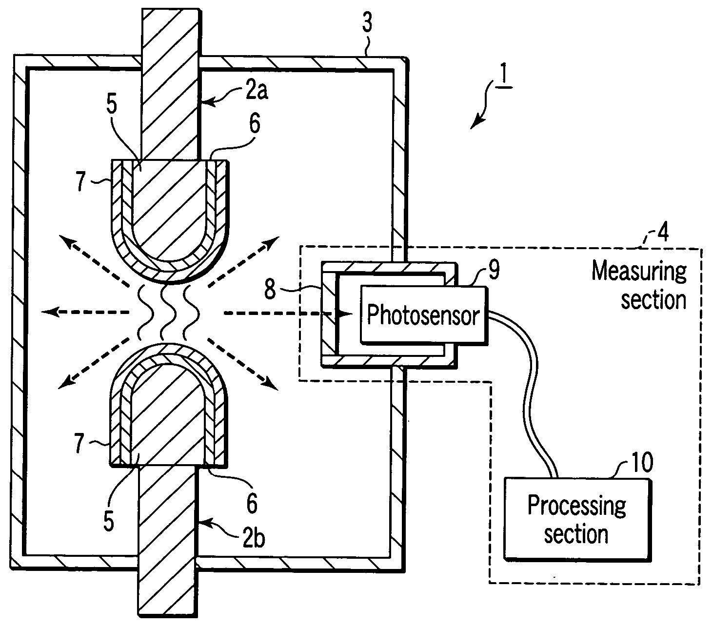
[0035]FIG. 1 is a vertical sectional view of the electric contact apparatus according to the first embodiment, which is denoted by reference numeral 1.
[0036] The electric contact apparatus 1 comprises a pair of electric contacts 2a and 2b, a housing 3, and a measuring section 4. In the electric contact apparatus 1, abrasion of the electric contacts 2a and 2b is detected.
[0037] The distal end portions of the electric contacts 2a and 2b are provided in the housing 3. The electric contacts 2a and 2b perform an electrical opening and closing operation for opening...
Example
THE SECOND EMBODIMENT
[0078] The second embodiment will be explained as a modification of the first embodiment.
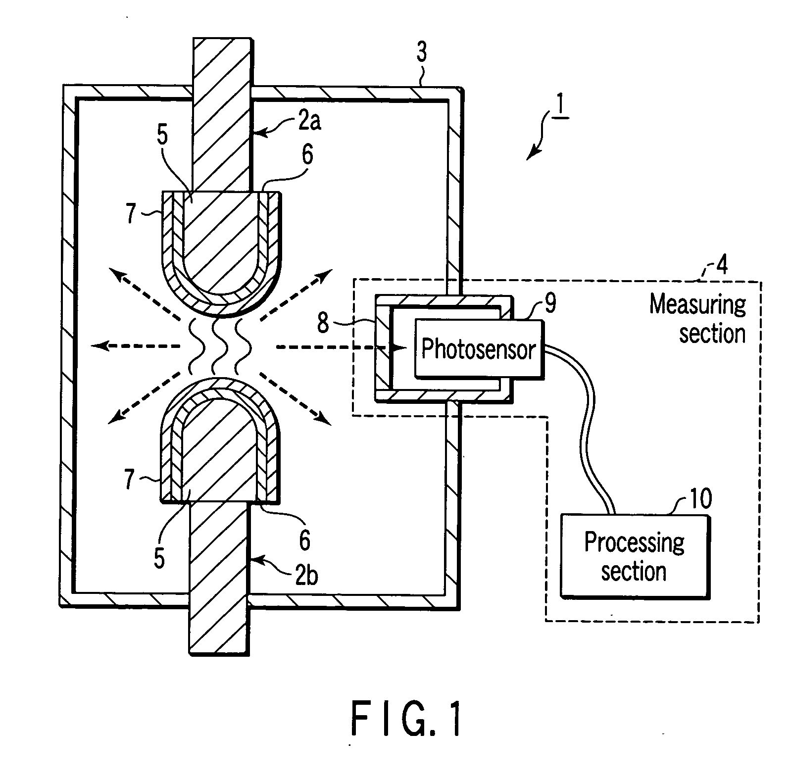
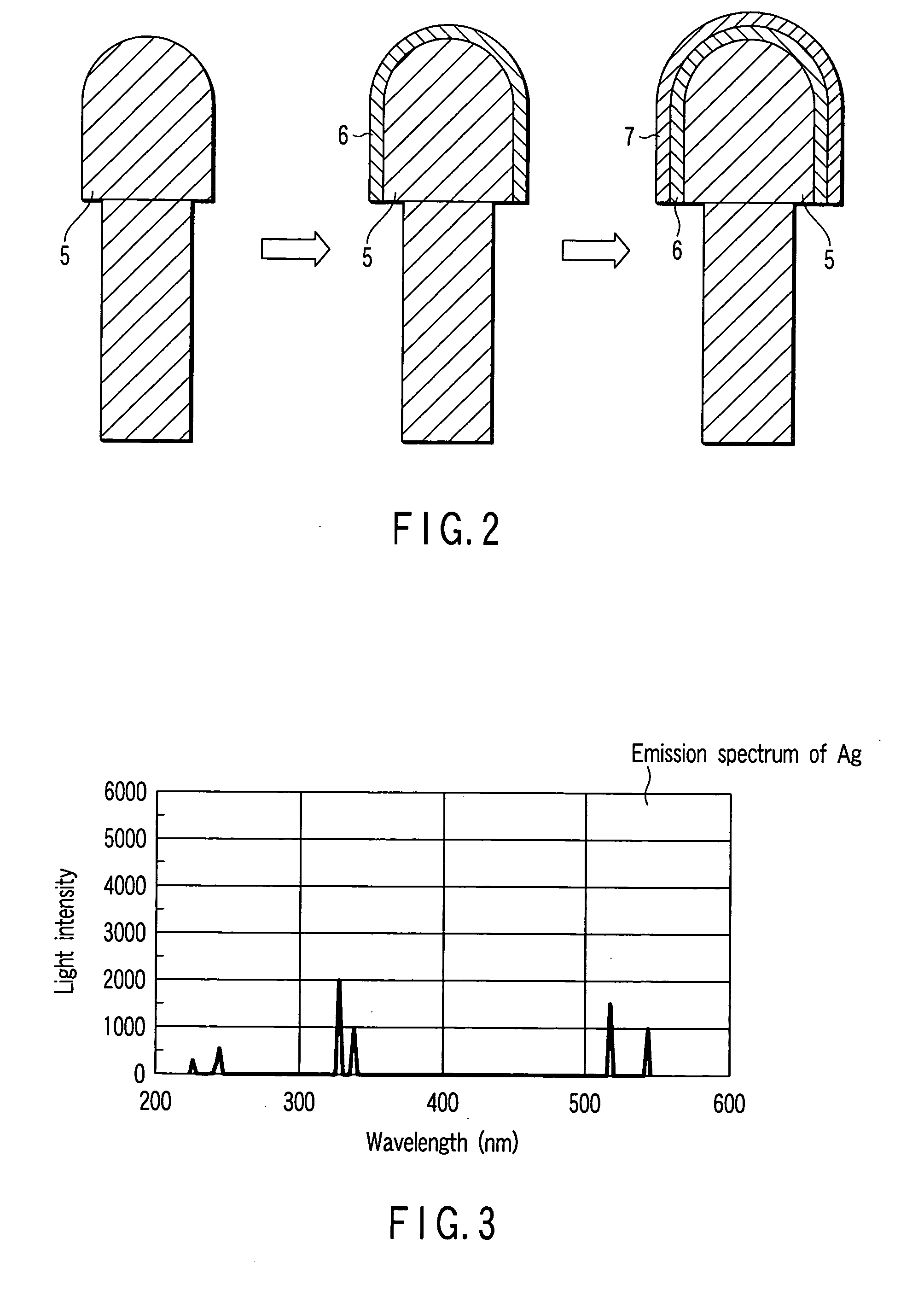
[0079] In the second embodiment, surface processing layers are provided on distal end portions of base material portions, and abrasion is detected when light emission at the opening and closing time of the electric contacts is changed from light emission of the surface processing layers to that of the base material portions.
[0080]FIG. 8 is a vertical sectional view of an example of an electric contact apparatus according to second embodiment of the present invention, which is denoted by reference numeral 11.
[0081] More specifically, in the second embodiment, the electric contact apparatus 11 comprises the electric contacts 12a and 12b, the housing 3 and a measuring section 13.
[0082] The electric contacts 12a and 12b comprise base material portions 14 and surface processing layers 15.
[0083] In the second embodiment, the boundaries between the base material portions 14 a...
Example
THE THIRD EMBODIMENT
[0097] The third embodiment will be explained as another modification of the first embodiment. In electric contacts in the third embodiment, holes are formed in the distal end portions of base material portions, indication portions are provided in abrasion detection positions in the holes, and the holes are covered with caps.
[0098]FIG. 9 is a vertical sectional view of an example of electric contacts in the third embodiment.
[0099] In the third embodiment, electric contacts 18 comprise base material portions 19 and indication portions 20.
[0100] The base material portions 19 comprise base material bodies 19a and caps 19b.
[0101] Holes are formed in the base material bodies 19a of the base material portions 19 at the distal ends of the electric contacts 18. In the holes, the indication portions 20 are provided. The caps 19b close opening portions of the holes. As a result, the indication portions 20 are held in the base material portions 19. The boundaries betwe...
PUM
 Abstract
Description
Claims
Application Information
 - R&D Engineer
- R&D Manager
- IP Professional
- Industry Leading Data Capabilities
- Powerful AI technology
- Patent DNA Extraction
Browse by: Latest US Patents, China's latest patents, Technical Efficacy Thesaurus, Application Domain, Technology Topic.
© 2024 PatSnap. All rights reserved.Legal|Privacy policy|Modern Slavery Act Transparency Statement|Sitemap