Method of nesting three-dimensional print objects

a three-dimensional print object and print object technology, applied in the field of three-dimensional print object nesting, can solve the problems of observed quality issues, observed quality issues, and inverse correlation of prior art quality issues with the height of printed objects, so as to achieve the effect of reducing curing intensity, reducing curing intensity, and reducing the quality of printed objects

Active Publication Date: 2018-11-15
OCE HLDG BV
View PDF0 Cites 8 Cited by
  • Summary
  • Abstract
  • Description
  • Claims
  • Application Information

AI Technical Summary

Benefits of technology

[0013]An advantage of the present invention is obtained in cases where curing means such as radiation sources are carried on the print heads or on a print head carriage. In that case, in order to obtain a high print quality, it is required that the intensity of curing is adjusted properly and is neither too large nor too small. When the print objects are arranged on the print surface without paying attention to the heights of the objects, higher and lower print objects will be interleaved on the print surface, and when the print head and the curing means scan the print surface while printing the top layers of the higher objects, the top surfaces of the less high objects which had been cured already will be cured again and again, so that the curing intensity may become too high, and the print quality will be degraded. Since, according to the invention, the higher objects are grouped together, the top layers of the higher objects can be printed while the scan movements of the print head are confined to the restricted area where the higher objects are located, and over-curing of the less high objects can be avoided.
[0014]By grouping objects to be printed with a similar height and arrange these groups such that they extend in the direction of the main scanning direction of the print head, all objects produced during the same main scan movements have a similar height and the building up of these objects completes after a more-or-less similar amount of passes by the print head resulting in the proper amount of curing for all objects.
[0015]The method according to the invention, requiring that objects with equal or similar height are grouped together, may lead to a configuration which may be not quite as compact as would be achieved with conventional nesting algorithms which disregard the height of the objects, but the invention has the additional advantage that it permits to reduce the distance of travel of the print head because, when the print objects with a lower height have been completed, the print head needs to scan only those shelves of the print surface which contain objects with a larger height. Moreover, the objects with lower height will generally be formed at locations which are remote from the area where the higher objects are still being printed, and it is therefore possible to cut the print substrate (if the objects are printed on a common media sheet), to remove the printed objects from the print surface and to package them while the printer is still busy with printing the higher objects (or vice versa), and yet there is no substantial risk that an operator or tools used for cutting or removing the printed objects collide with the print head.
[0016]The printer used for carrying out the invention is of a type wherein the print head moves in a main scanning direction along a gantry and the gantry moves relative to the print surface in a sub-scanning direction normal to the main scanning direction. The print objects with equal or similar height are aligned in the main scanning direction, whereas objects with significantly different heights are offset relative to one another in the sub-scanning direction. The print head may then perform complete scan passes in the main scanning direction, which assures a high positional accuracy of the ink dots being printed, and the scanned area can be confined by limiting the range in which the gantry moves in the sub-scanning direction.
[0017]The print surface is divided into stripe-shaped areas which extend in the main scanning direction and are designated as “shelves” hereinafter. Print objects of different heights are nested in different shelves, so that the print objects within a shelf will always have essentially the same height. Then, for nesting the objects within a single shelf, it is possible to use the well known and readily available nesting algorithms that are presently being used in two-dimensional printing.
[0018]Depending upon the type of ink and the curing method, certain height differences between the print objects within the same shelf may be tolerated. In that case the required number of shelves may be smaller than the number of different object heights occurring in the set of objects to be printed. Consequently, the size of the shelves will be larger which makes the conventional two-dimensional nesting algorithms more powerful.

Problems solved by technology

The quality issues observed with the prior art methods were actually inversely correlated with the height of the printed objects.
Even more specific; it appeared that printed objects in proximity to other and higher printed objects were more prone to these quality issues.
Further investigation showed that the observed quality issues were caused by overcuring of the lower printed objects.
However, it cannot be completed prevented that the ink of the lower, already printed object is at least partly cured too during the same curing operation resulting in overcuring of the lower, already printed object.
The excessive amount of curing occurring thus results to some extent in colour deviation, volume changes, and surface cracking.

Method used


Image

  • Method of nesting three-dimensional print objects
  • Method of nesting three-dimensional print objects
  • Method of nesting three-dimensional print objects

Examples


Embodiment Construction

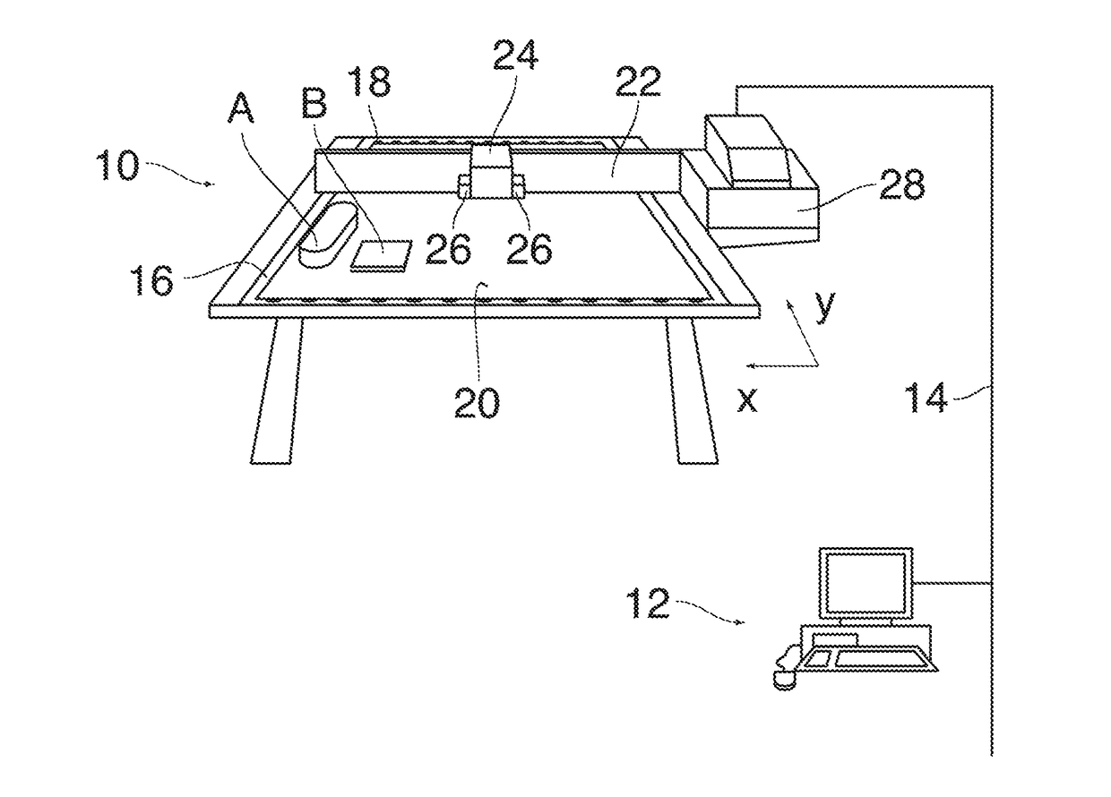
[0027]FIG. 1 shows a printing system comprising a flat bed printer 10 and a workstation 12 connected to the printer via a network 14 and permitting to compile and edit print jobs to be executed with the printer 10.

[0028]The printer 10 has a flat bed with a rectangular print surface 16 in which a regular pattern of suction holes 18 has been formed. The suction holes are connected to a vacuum source, so that a print substrate 20, e.g. a rectangular sheet of paper, can be sucked against the print surface so as to be immobilized on the flat bed.

[0029]A gantry 22 extends across the print surface 16 in a main scanning direction x and is itself movable relative to the print surface in a sub-scanning direction y. A print head 24, e.g. an ink jet print head, is driven for reciprocating movement along the gantry 22 in the main scanning direction x and is controlled to eject a curable ink, e.g. UV-curable ink, onto the print substrate 20 in several superposed layers so as to form three-dimensi...


PUM

PropertyMeasurementUnit
sizeaaaaaaaaaa
surface areaaaaaaaaaaa
constant widthaaaaaaaaaa

Abstract

A method of nesting three-dimensional print objects on a print surface of a printer, wherein the locations for the print objects on the print surface are determined in view of the shape and size of the footprints of the objects so as to minimize the surface area required for accommodating the objects, and the locations for the print objects are determined also in view of intended heights of the objects, and objects with equal or similar height are grouped together, the method comprising a step of grouping the objects into classes of objects with similar heights, and a step of nesting the objects class by class, wherein the method is performed on a printer having a print head movable relative to the print surface in a main scanning direction and sub-scanning direction normal to the main scanning direction, and wherein the objects of each class are nested in a separate shelf that extends in the main scanning direction on the print surface and has a constant width in the sub-scanning direction.

Description

CROSS REFERENCE TO RELATED APPLICATIONS[0001]This application claims priority under 35 U.S.C. § 119(a) to application Ser. No. 17170107.1, filed in Europe on May 9, 2017, the entire contents of which is hereby incorporated by reference into the present application.BACKGROUND OF THE INVENTIONField of the Invention[0002]The invention relates to a method of nesting three-dimensional print objects on a print surface of a printer, wherein the locations for the print objects on the print surface are determined in view of the shape and size of the footprints of the objects so as to minimize the surface area required for accommodating the objects, and the locations for the print objects are determined also in view of intended heights of the objects, and objects with equal or similar height are grouped together, the method comprising a step of grouping the objects into classes of objects with similar heights, and a step of nesting the objects class by class.Background of the Invention[0003]N...

Claims


Application Information

Patent Timeline
Patent Type & Authority Applications(United States)
IPC IPC(8): G06F3/12H04N1/00B33Y50/00B29C64/386B33Y30/00B29C64/20
CPCG06F3/1208G06F3/1206G06F3/1297G06F3/1248H04N1/0066B33Y50/00B29C64/386B33Y30/00B29C64/20B33Y10/00B29C64/112G06F30/00G06F2119/18Y02P90/02B29C64/393G06F2113/12
Inventor COLLOMP, JEROME
Owner OCE HLDG BV
Why Eureka
Try Eureka