Developer carrier, developing device, image forming apparatus and computer system

a developing device and computer system technology, applied in the direction of electrographic process apparatus, instruments, optics, etc., can solve the problems of uneven pressure in the longitudinal direction, uneven density, and deformation of the developing roller, etc., to achieve stable supply, easy adjustment of proper contact pressure, and high printing quality

Inactive Publication Date: 2005-08-25
SEIKO EPSON CORP
View PDF2 Cites 57 Cited by
  • Summary
  • Abstract
  • Description
  • Claims
  • Application Information

AI Technical Summary

Benefits of technology

[0154] An electric-contact urging device on a rotation shaft according to the invention is that an electric-contact urging device according to the invention is provided on one conductor elastic plate. According to the invention, by one conductor elastic plate, it is possible to easily adjust a proper contact pressure of the electric contacts with a plurality of rotation shafts.
[0155] A developing device of the invention has an electric-contact urging device on a rotation shaft as described above. According to the invention, because charged state can be stabili

Problems solved by technology

Also, although the developing roller rotates around the central axis thereof, deflection occurs in the developing roller due to this rotation.
Additionally, the fluctuation in image density leads to unevenness of density having a periodicity and becomes visible.
However, because spot welding is ordinarily done by welding at plural points, of the positions in the longitudinal direction of the regulation blade, the pressure differs between the positions where spot welding has been conducted and the positions where spot welding has not been conducted, and there is the potential for the pressure in the longitudinal direction to become uneven.
Additionally, because the regulation blade is fixed to the support member, the rigidity of the support member is weak, and if flexure occurs in the support member, there is the potential for flexure to also occur in the regulation blade and for the pressure to become uneven.
Further, there is the potential for uneven pressure of the regulation blade arising as a result of these causes being compounded to cause the charge of the toner to become uneven, and such unevenness of the charge triggers drawbacks such as image deterioration, toner leakage and toner scattering.
If such heat accumulates within the developing cartridge, the toner is denatured by temperature rise, thus causing an adverse effect upon the quality of printing.
Consequently, there encounters softening by the heat of friction or the like caused upon driving various constituent elements including rotating gears, readily causing a deformation in the housing part under the application of a load.
With such a load application, there is a problem that the thermally softened end face of the developing cartridge is pushed into deformation.
This results in a posi

Method used


Image

  • Developer carrier, developing device, image forming apparatus and computer system
  • Developer carrier, developing device, image forming apparatus and computer system
  • Developer carrier, developing device, image forming apparatus and computer system

Examples


first embodiment

===Example of Overall Configuration of Image Forming Apparatus===

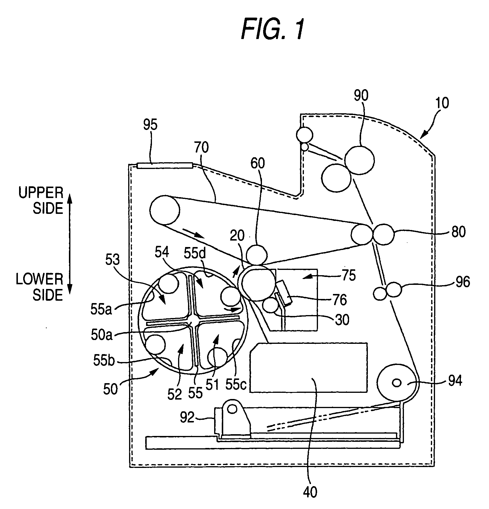
[0216] Next, using FIG. 1, an overview of an image forming apparatus of the first embodiment will be described below using a laser beam printer (referred to below as a printer) 10 as an example. FIG. 1 is a diagram showing the main constituent elements configuring the printer 10. It should be noted that, in FIG. 1, upper and lower directions are represented by arrows. For example, a sheet supply tray 92 is disposed in a lower portion of the printer 10 and a fixing unit 90 is disposed in an upper portion of the printer 10.

[0217] As shown in FIG. 1, the printer 10 pertaining to the present embodiment includes, along the rotational direction of a photosensitive body 20 serving as an example of an image carrier that carries a latent image, a charging unit 30, an exposure unit 40, a YMCK development unit 50, a primary transfer unit 60, an intermediate transfer body 70 and a cleaning unit 75, and further includes a seconda...

second embodiment

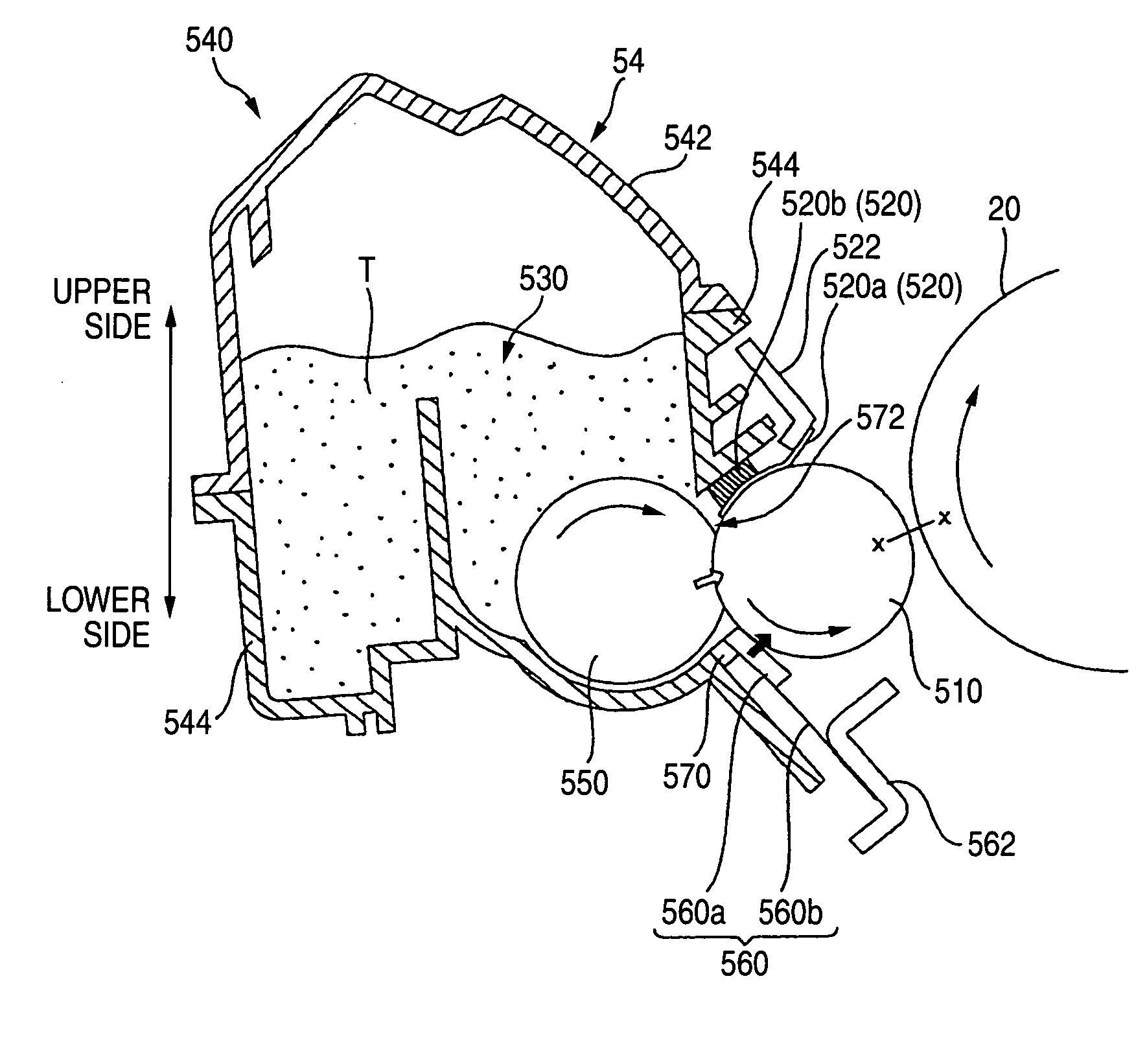
[0359] Second embodiment of the present invention will now be explained on the basis of the drawings. FIG. 24 is a side sectional view showing an image forming apparatus provided with a heat releasing device in a developing cartridge (developing device according to the present invention). FIG. 25 is a perspective view of a rotary development unit. FIG. 26 is a perspective view showing the upper and lower housing members in a state they are opened in the direction of the arrows. FIG. 27 is a side sectional view of the developing cartridge. Meanwhile, FIGS. 28A and 28B are explanatory views showing the toner movement within the cartridge as the rotary development unit is rotated from a state of FIG. 28A to a state of FIG. 28B, wherein notice is taken to the two developing cartridges.

[0360] Furthermore, FIG. 29A is a front view showing the entire roller support frame, FIG. 29B is an enlarged view of a left part of the roller support frame, and FIG. 29C is a side sectional view showing...

third embodiment

[0443] Third embodiment of the invention will be described below with reference to drawings. FIG. 50 is a whole constitutional diagram showing one example of an image forming apparatus to which a developing device of the invention is applied.

[0444] In this image forming apparatus, a photosensitive drum 602 served as image carrier is arranged in an apparatus main body 601 and it is driven by a not-shown drive unit in a direction of an arrow D1. Around this photosensitive drum 602, a charging unit 603 for charging the photosensitive drum 602 uniformly, an exposure unit 604, a rotary development unit 605, a transfer unit 606, and a cleaning unit 607 are respectively arranged in the rotational direction D1.

[0445] In the rotary development unit 605, a yellow developing device 605Y, a magenta developing device 605M, a cyan developing device 605C and a black developing device 605K are provided rotatably about a rotary shaft 612 by a drive unit (not shown). A developing roller 614 in one ...


PUM


Abstract

A developer carrier for carrying a developer, the developer carrier comprises: an opposing region that opposes a latent image-carryable region on an image carrier, and a solid portion that is solid at an end portion of the developer carrier in a longitudinal direction thereof; wherein an end of the solid portion, which is on a side of a center of the developer carrier in the longitudinal direction, is located closer to the center of the developer carrier than an edge of the opposing region.

Description

[0001] The present application is based on Japanese Patent Applications Nos. 2002-336504, 2002-338500, 2002-340500, 2002-347538, 2002-357472, 2002-357476, 2002-357485, 2003-005719 and 2003-018291, the entire contents of which are incorporated herein by reference. BACKGROUND OF THE INVENTION [0002] 1. Field of the Invention [0003] The present invention relates to a developer carrier, a developing device, an image forming apparatus and a computer system. [0004] More specifically, the present invention relates to a developing device used in an image forming apparatus, in which toner is attached onto an electrostatic latent image formed on an image carrier to make the image visible. [0005] 2. Related Art [0006] As this type of image forming apparatus, image forming apparatuses are known, for example as disclosed in Japanese Patent Publications Nos. JP S63-58384A and JP H10-48933A, that include plural developing devices that develop a latent image formed on a photosensitive body as an ex...

Claims


Application Information

Patent Timeline
IPC IPC(8): G03G15/06G03G15/08
CPCG03G15/065G03G15/0812G03G15/0813G03G2215/0872G03G15/0896G03G15/0898G03G2215/0177G03G15/0817
Inventor OKAMOTO, KATSUMI
Owner SEIKO EPSON CORP
Why Eureka
Try Eureka