Meltable ink for an inkjet printer and a method of selecting such an ink

a technology of inkjet printer and ink drop, which is applied in the field of meltable ink, can solve the problems of insufficient cohesion of ink, adverse effect on print quality, and inability to obtain print quality of this kind with a direct printing process, and achieves small thermal capacity of an individual drop of ink, sufficient cohesion, and specific visco-elastic properties

Inactive Publication Date: 2005-08-02
OCE TECH
View PDF7 Cites 57 Cited by
  • Summary
  • Abstract
  • Description
  • Claims
  • Application Information

AI Technical Summary

Benefits of technology

[0003]An ink of this kind (also known as a hot melt ink) is disclosed in U.S. Pat. No. 5,372,852. The ink is printed indirectly, i.e. via an intermediate transfer element, on a receiving material, for example, a sheet of paper or a plastic overhead sheet. For this purpose, the temperature of the ink is raised so that it is liquid, whereafter the liquid ink is transferred imagewise by means of an inkjet printhead on to a liquid transfer surface applied to the transfer element, for example, a thin layer of silicone oil applied to a metal roller. The temperature of the transfer element is lower than the melting temperature of the ink, but higher than room temperature. As soon as the ink is transferred to the transfer element, it will cool and finally assume a solid consistency. Because of the small thermal capacity of an individual ink drop, it often cools very rapidly so that its temperature is practically immediately equal—at least for an appreciable part—to the temperature of the transfer element. The ink is of a composition such that under the conditions indicated hereinbefore, and particularly at the temperature of the transfer element, it is malleable and has specific visco-elastic properties which make it possible for the ink to be pressure-transferable, i.e., under pressure and in a certain temperature range it is sufficiently deformable to fuse on a receiving material but also has sufficient cohesion not to split during the transfer (cohesive fa

Problems solved by technology

At a temperature higher than the top limit, the ink is insufficiently cohesive and will split during the transfer process.
As a result, some of the ink will remain on the transfer element, and this has an adverse effect on print quality.
A print quality of this kind cannot be obtained with a direct printing process, i.e., a printing process in which ink drops are applied to a receiving material directly by means of a printhead.
However, the known pressure-transferable inks have one significant disadvantage.
It has been found that the ink transfers relatively unsatisfactorily from the transfer element to the receiving material.
Under these conditions the liquid also partially transfers to the receiving material because this liquid exhibits cohesive failure on transfer of the ink drops to the receiving material.
The need for a “sacrifice layer” of this kind makes the printing process very complex because t

Method used


Image

  • Meltable ink for an inkjet printer and a method of selecting such an ink
  • Meltable ink for an inkjet printer and a method of selecting such an ink
  • Meltable ink for an inkjet printer and a method of selecting such an ink

Examples


example 1

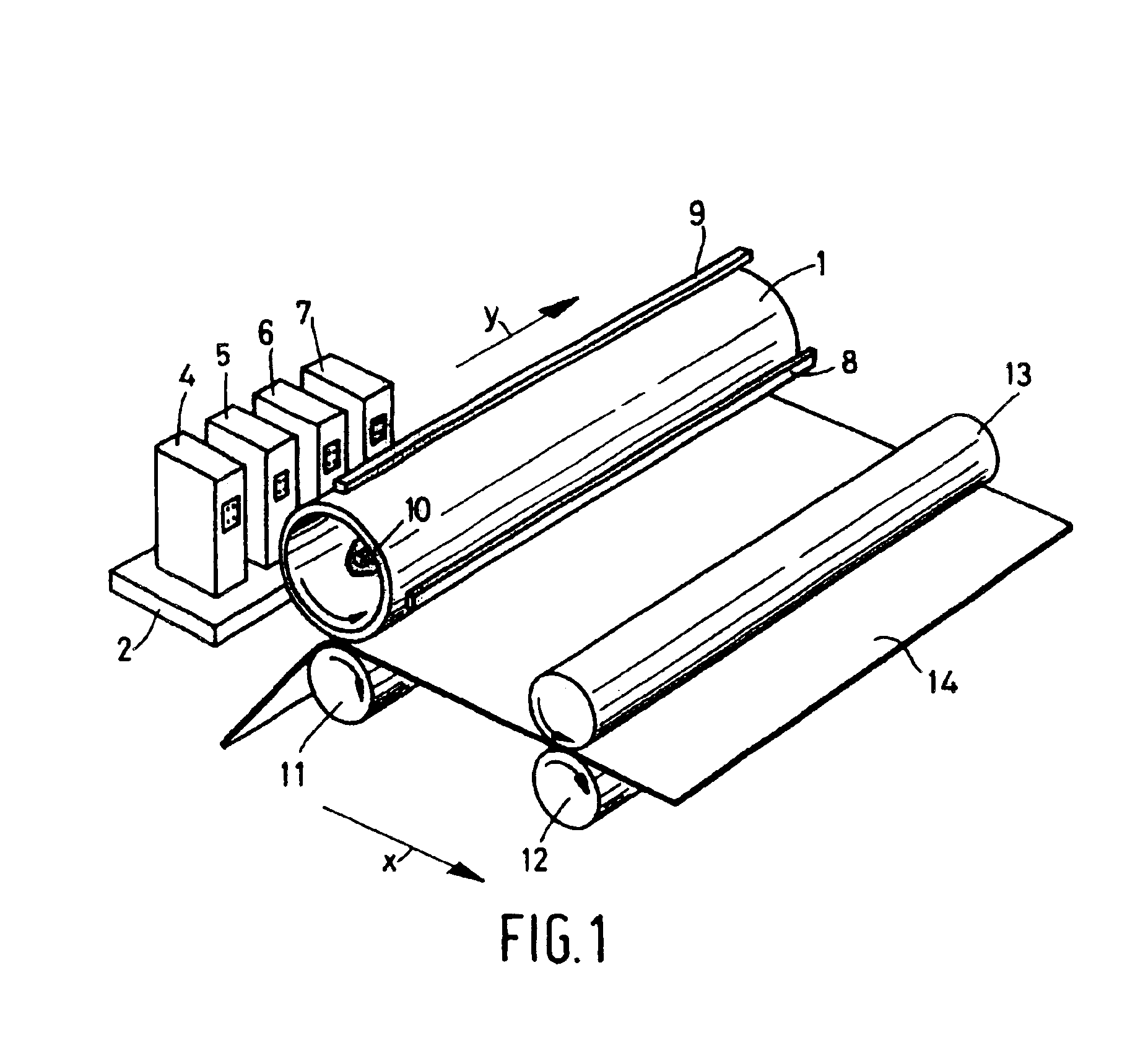
[0030]FIG. 1 diagrammatically shows the most important parts of an indirect inkjet method as known from the prior art. The transfer element 1 is disposed centrally in this process and in this case is a hollow aluminum roller. This roller is kept at an elevated temperature by means of a radiator 10 which selectively heats a specific area of the roller. The temperature is kept constant within a margin of a number of degrees by means of a temperature control system (not shown), in such manner that the temperature remains within the bottom limit and the top limit at which the ink is pressure-transferable. The transfer element is provided with a feed element 9 disposed at a distance and serving to provide the surface of the roller with a layer of silicone oil. An image is printed on this layer, which serves as a sacrifice layer, by means of a number of printheads (4, 5, 6 and 7, one for each of the colors cyan, magenta, yellow and black) disposed on a carriage 2. This can be carried out ...

example 2

[0031]It is not possible to predict beforehand whether a specific meltable ink is pressure-transferable. The literature discloses analytical methods to determine whether a specific ink is pressure-transferable, for example U.S. Pat. No. 5,372,852 and the Journal of Imaging Science and Technology, Vol. 40, No. 5, September / October 1996, pages 386 to 389. However, it is also possible to subject a specific ink to a practical test. For this purpose, it is possible to use a printing system which applies an indirect inkjet process as the method. In this example, a generally available printer is used, namely the Phaser 840 Xerox printer. The ink concerned is loaded in the inkjet printhead of this printer and then printing is carried out. It is also possible to use a different printhead to apply the ink to the transfer element, for example, a printhead specially developed to use the ink under test. In principle, any method of applying a thin layer of ink (typically 10 to 100 μm) to the tran...

example 3

[0033]This Example indicates how the transfer yield can be determined at a specific temperature and, if there is a transfer working range, what the top and bottom temperature limits of such range are.

[0034]An explanation will first be given as to how the transfer yield can be determined at a specific temperature of the transfer element. The transfer yield is defined as the optical density of a printed image in the case of a single transfer (i.e., the receiving material has been in contact with the image on the transfer element only once), divided by the optical density in the case of a 100% transfer:

ηT=(OD)T,1 / (OD)100%  (1)

where ηT is the transfer yield at a temperature T of the transfer element, (OD)T,1 is the optical density of a single transfer at a temperature T of the transfer element and (OD)100% is the optical density in the case of a 100% transfer. (OD)T,1 is measured with a Gretag densitometer (Gretag D183 OD-meter) by measuring the optical density of the image as transferr...


PUM

PropertyMeasurementUnit
Dynamic viscosityaaaaaaaaaa

Abstract

A meltable ink which is solid at room temperature, which ink is suitable for use in an indirect printing process, in which printing process the ink is transferred, by the use of an inkjet printhead, to a transfer element, whereafter the ink is transferred to a receiving material under pressure from the transfer element, the ink having a composition such that it is pressure-transferable at a temperature between a bottom temperature limit and a top temperature limit, wherein the ink has a deformation energy of less than 20×105 Pa.s at a temperature equal to said top temperature limit.

Description

[0001]This non-provisional application claims priority under 35 U.S.C. 119(a) on Dutch Patent Application No. 1021011, filed in The Netherlands on Jul. 5, 2002, the contents of which are hereby incorporated by reference.BACKGROUND OF THE INVENTION[0002]The present invention relates to a meltable ink which is solid at room temperature, which ink is suitable for use in an indirect printing process. In this printing process, the ink is transferred, by the use of an inkjet printhead, to a transfer element, whereafter the ink is transferred to a receiving material under pressure from the transfer element. The ink has a composition such that it is pressure-transferable at a temperature between a bottom limit and a top limit. The invention also relates to a method of selecting a meltable ink for use in such a printing process.SUMMARY OF THE INVENTION[0003]An ink of this kind (also known as a hot melt ink) is disclosed in U.S. Pat. No. 5,372,852. The ink is printed indirectly, i.e. via an i...

Claims


Application Information

Patent Timeline
IPC IPC(8): C09D11/00B41J2/01B41M5/00
CPCC09D11/34
Inventor KREMERS, MARTINUS ANTONIUSTHIJSSEN, MAURICE HENDRIKUS HUBERTINUSWEITENAUER, BERBY MARGA GERARDA
Owner OCE TECH
Why Eureka
Try Eureka