Screen printing apparatus and method

a technology of printing apparatus and screen, applied in the direction of printing, printing, printed circuit manufacture, etc., can solve the problems of uneven print uniformity, reduced life of printing screen, uneven print quality across the area of printed substrate, etc., to improve separation between printing screen and substrate, reduce the tension applied to the screen, and improve the effect of separation

Inactive Publication Date: 2018-01-18
ASM ASSEMBLY SYST SINGAPORE PTE LTD
View PDF7 Cites 2 Cited by
  • Summary
  • Abstract
  • Description
  • Claims
  • Application Information

AI Technical Summary

Benefits of technology

[0007]In accordance with the present invention, it has been discovered that this aim may be achieved by providing a mechanism for moving at least a portion of the printing screen relative to its normal plane. By moving the screen away from the substrate after printing, improved separation between the printing screen and substrate can be achieved. By moving the screen towards the substrate before printing, the screen can be pre-tensioned so that the tension which the print head has to overcome is reduced. Finally, by controlled movement of the screen towards and away from the substrate, it is possible to reduce tension applied to the screen, and thus improve its working life.
[0008]In a preferred embodiment, the separation or peel-off of the printing screen from the substrate is controlled independently of the print speed and the print gap, thereby de-coupling the separation or peel-off from the print speed and the print gap, and so enabling optimisation of the peel-off in relation to the print speed. It is believed that peel-off has a greater effect on print quality than print speed, and, by independently controlling the peel-off, this aspect of the present invention enables the application of greater print speeds at the same separation or peel-off speed and yet maintains print quality, or enables the application of greater print speeds at a slower separation or peel-off speed and provides for improved print quality.
[0009]In another preferred embodiment the printing screen is brought into contact with the substrate before the print stroke, which enables the print head to be applied with lower pressure, insofar as the print head does not have to overcome the tension of the printing screen, and this pressure is more evenly distributed over the substrate. The application of a lower pressure provides for improved print quality across the substrate, and also provides for the print head and the printing screen to have a longer life.
[0010]In a further preferred embodiment the printing screen can be configured to have a neutral position from which the printing screen is moved before the print stroke in a first direction, typically downwards, by a distance less than the required print gap into contact with the substrate to be printed, and subsequently moved in a second direction opposite to the first direction, typically upwards, by a distance corresponding to the balance of the print gap, whereby the full print gap is established to enable separation and with a movement of the printing screen from the neutral position which is less than a distance corresponding to the required print gap. With this arrangement, the elastic stress on the printing screen is much reduced, so providing the printing screen with increased life.

Problems solved by technology

Firstly, there is no direct control over separation of the printing screen and the substrate, known as peel-off, and this peel-off occurs faster at the edges of the image area than in the center of the image area, which has been noted to result in uneven print quality across the area of the printed substrate.
Secondly, the print head has to overcome the tension of the printing screen to apply pressure to the substrate, giving rise to an uneven print uniformity, because the resistance to travel of the print head is greater at the ends of the print head than in the center of the print head.
Thirdly, the life of the printing screen is reduced, because in every print cycle, some of the printing screen must be moved by a distance corresponding to the required print gap between the printing screen and the substrate, which progressively causes a loss of tension in the printing screen, leading to variation in print quality over the life of the printing screen as the tension decreases, and ultimately premature failure of the printing screen.

Method used


Image

  • Screen printing apparatus and method
  • Screen printing apparatus and method
  • Screen printing apparatus and method

Examples


first embodiment

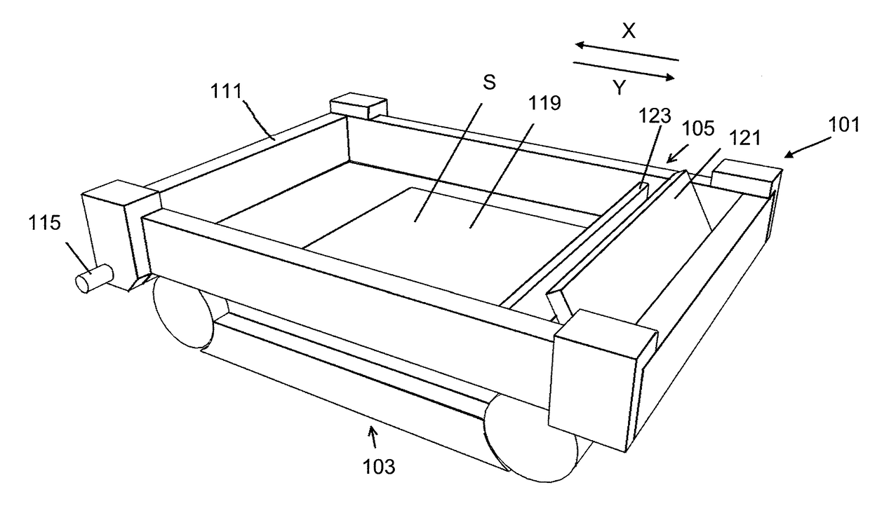
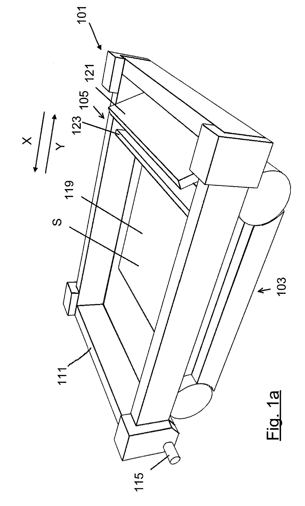
[0053]FIGS. 1(a) and (b) illustrate a screen printing apparatus in accordance with the present invention.

[0054]The screen printing apparatus comprises a printing screen unit 101 through which a print medium is printed onto a substrate S, a support 103, in this embodiment in the form of a platen, here disposed beneath the printing screen unit 101, on which the substrate S is supported during printing, and a print head 105, which is operative in a print stroke to print print medium onto the substrate S.

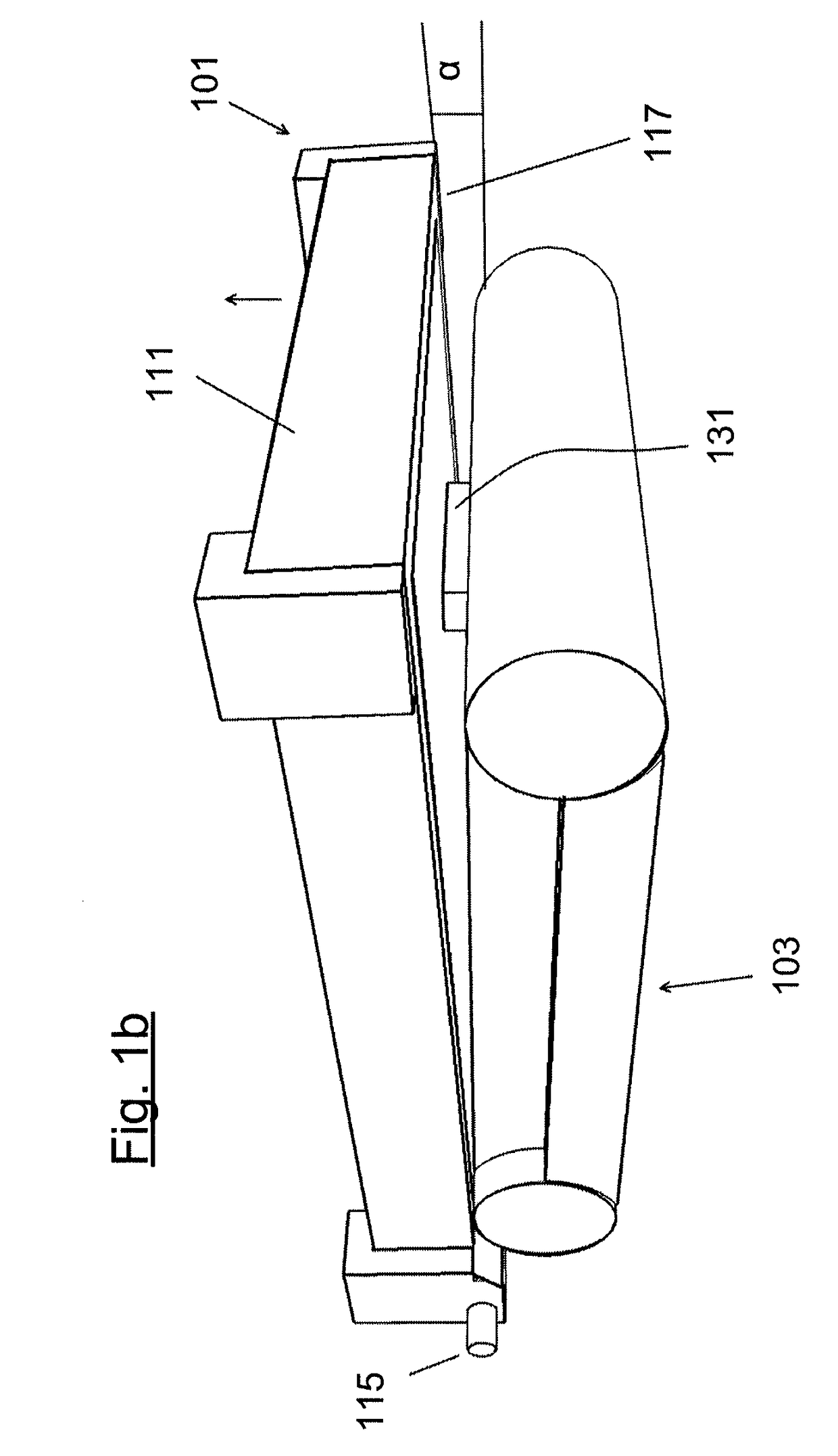
[0055]The printing screen unit 101 comprises a frame 111, in this embodiment of rectangular shape, which is pivotable about a pivot 115 at one edge of the frame 111, and a printing screen 117 which is mounted under tension to the frame 111.

[0056]In this embodiment the printing screen unit 101 is pivoted about the pivot 115 by operation of an actuator (not illustrated), which acts to move the printing screen 117 away from the substrate S, in this embodiment upwardly in relation to the su...


PUM


Abstract

A screen printing apparatus for screen printing onto a substrate comprises: a printing screen unit, with a printing screen and a frame for holding the printing screen in a substantially planar primary configuration; a support for the substrate; and a moveable print head for contacting and sweeping across a printing region of a first surface of the printing screen; an engagement structure mounted to contact a region of a surface of the printing screen which lies outside any part of the printing region which is drivable to move a portion of the printing screen in a direction orthogonal to the screen. Moving the screen away from the substrate improves separation between the printing screen and substrate. Moving the screen towards the substrate before printing can pre-tension the screen to reduce the tension which the print head has to overcome. Controlled movement of the screen towards and away from the substrate can reduce tension applied to the screen, and thus improve its working life.

Description

TECHNICAL FIELD[0001]The present invention relates to a screen printing apparatus and a method for screen printing through a printing screen onto a substrate, typically an electronics substrate, such as a wafer for solar or fuel cells or a circuit board, using a print head, typically comprising a squeegee.BACKGROUND OF THE INVENTION[0002]Various screen printing apparatus and methods already exist. However, the present inventor has recognized that these apparatus and methods suffer from a number of drawbacks.[0003]Firstly, there is no direct control over separation of the printing screen and the substrate, known as peel-off, and this peel-off occurs faster at the edges of the image area than in the center of the image area, which has been noted to result in uneven print quality across the area of the printed substrate.[0004]Secondly, the print head has to overcome the tension of the printing screen to apply pressure to the substrate, giving rise to an uneven print uniformity, because...

Claims


Application Information

Patent Timeline
Patent Type & Authority Applications(United States)
IPC IPC(8): B41F15/34
CPCB41F15/34B41F15/0881B41F15/26B41F15/36H05K3/1225H05K3/1233H05K2203/0139B41F15/0818B41F15/085B41P2215/112B41P2215/14B41P2215/13B41M1/12B41M5/41
Inventor FALCON, TOM
Owner ASM ASSEMBLY SYST SINGAPORE PTE LTD
Why Eureka
Try Eureka