Recording apparatus

Active Publication Date: 2005-02-24
CANON KK
View PDF12 Cites 13 Cited by
  • Summary
  • Abstract
  • Description
  • Claims
  • Application Information

AI Technical Summary

Benefits of technology

[0007] It is one objective of the present invention to provide a recording apparatus that

Problems solved by technology

However, when a currently available general-purpose recording apparatus, is used for the printing of a recording member such as a CD, since the recording apparatus uses the same path for conveying the recording member as it uses for a cut sheet, the high rigidity of the recording member causes the performance of the conveying process to be degraded, and either the recording member is scratched or it is not conveyed because of the distance between the feed rollers.
However, the following technical problems have been encountered.
First, when edging at the end of the raised portion of the tray is not properly performed before the hot stamping, a reflection face edge can not be appropriately formed and detection errors may occur.
Therefore, the edg

Method used


Image

  • Recording apparatus
  • Recording apparatus
  • Recording apparatus

Examples


Example

[0061] (First Embodiment)

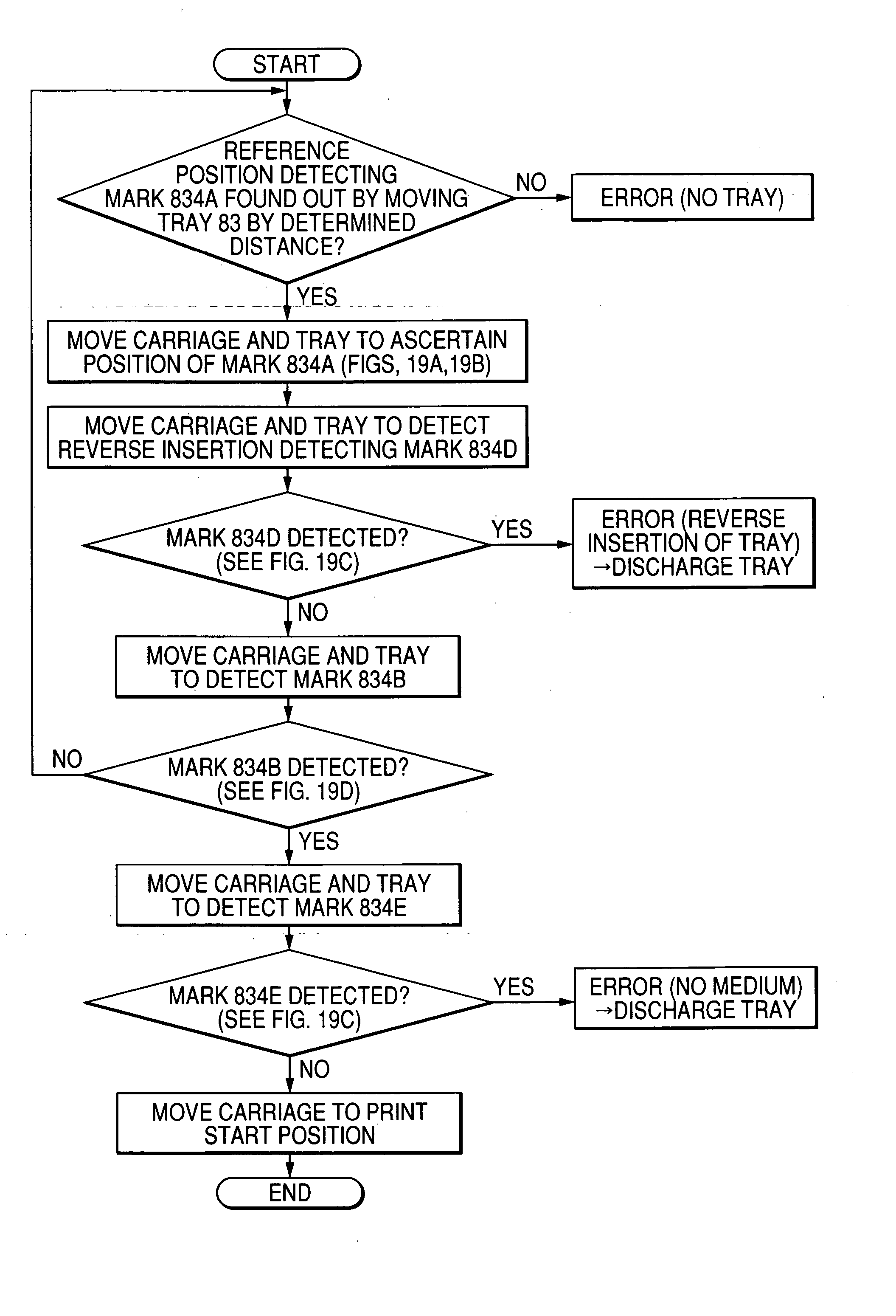
[0062] First, an explanation will be given for the structures of detection marks 834, according to a first embodiment, that function as portions to be detected. FIG. 14 is a vertical cross-sectional view of the structure of a reference position detection mark 834A according to the first embodiment. FIG. 15 is a plan view of a reflection plate of the reference position detection mark 834A in FIG. 14. FIG. 16 is a schematic vertical cross-sectional view of an example reference for the reference position detection mark 834A. FIG. 17 is a fragmentary plan view for explaining the relative position of a sensor 59 that functions as the position detection means according to the first embodiment. FIG. 18 is a graph showing as an example a change in the light intensity during the reflection plate detection process sequence for detecting the position of a tray 83 according to the first embodiment. FIGS. 19A, 19B, 19C, 19D, 19E and 19F are diagrams for explaining the o...

Example

[0090] (Second Embodiment)

[0091]FIG. 26 is a vertical cross-sectional view of the structure of a tray position detector according to a second embodiment of the present invention. FIG. 27 is a plan view, taken from the surface of a tray, of the tray position detector in FIG. 26. In FIGS. 26 and 27, as in the first embodiment, the edges of a reference position detection mark 834A are determined by vertical faces 837 formed on a tray 83. Therefore, accurate printing can be performed for a small, thick recording member such as a CD. However, a foreign substance, such as ink mist or dust, that is attached to a reflective face 834A1 may affect the detection accuracy. So long as the substance is attached to the center of the reflective face 834A1, it does not greatly affect the detection accuracy; however, where the substance attached near the vertical face 837, deterioration of the edge reading accuracy would occur.

[0092] Therefore, in the second embodiment, to evacuate part of such a s...


PUM


Abstract

Disclosed is a recording apparatus that can accurately detect the position of a recording member, such as thick paper or a CD-R, that is mounted on a tray, that can, as much as possible, protect to-be-detected portions from being scratched, and that can perform accurate printing using a simple structure. With a configuration wherein a recording member such as thick paper or a CD-R is mounted on a tray, and wherein the recording member is printed while the tray is conveyed, a reference position detection mark, which is a to-be-detected portion, is attached to the tray from the reverse face, and the edges of a reference position detection mark that has been detected are made as the edges of a hole portion that is formed in the tray.

Description

BACKGROUND OF THE INVENTION [0001] 1. Field of the Invention [0002] The present invention relates to a recording apparatus, such as a printer, and to such a recording apparatus that is capable of recording a recording member mounted on a tray with conveying the tray. [0003] 2. Related Background Art [0004] As recording materials to be recorded by recording apparatuses, such as printers, there have been proposed a variety of media types, including small, thick recording members such as CD-Rs, DVDs and cards (hereinafter, collectively referred to as compact disks or CDs). However, when a currently available general-purpose recording apparatus, is used for the printing of a recording member such as a CD, since the recording apparatus uses the same path for conveying the recording member as it uses for a cut sheet, the high rigidity of the recording member causes the performance of the conveying process to be degraded, and either the recording member is scratched or it is not conveyed b...

Claims


Application Information

Patent Timeline
IPC IPC(8): B41J2/175B41J3/407B41J13/14B41J29/02B41J29/13B41J29/393B65H1/26
CPCB41J2/17546B41J3/4071B41J29/393B41J29/02B41J29/13B41J13/14
Inventor KAWAGUCHI, KOICHIRO
Owner CANON KK
Why Eureka
Try Eureka