
Stopwatch and watch

a technology of stopwatch and timepiece, which is applied in the direction of electric winding, instruments, and horology, can solve the problems of friction and slipping repeatedly occurring between the seconds wheel, the inability to make a more precise measurement, and the inability to accurately measure the time of the chronograph

Inactive Publication Date: 2005-02-24
SEIKO EPSON CORP
View PDF10 Cites 18 Cited by
  • Summary
  • Abstract
  • Description
  • Claims
  • Application Information

AI Technical Summary

Benefits of technology

[0012] The timepiece relating to the present invention has basic timepiece pointers, chronograph information pointers, a mechanical energy storage section, a train wheel, a power generator, and a control section. The basic timepiece pointers are provided in order to rotate and to indicate the standard time. The chronograph information pointers are provided in order to rotate and to indicate chronograph information. The mechanical energy storage section contains a mainspring. ...

Problems solved by technology

However, when the oscillation frequency of the balance is six oscillations, the smallest unit in the chronograph display is ⅙ seconds, but many specifications provide for graduations on the dial that are actually ⅕ seconds, which results in a problem in that the indicating tip of the second CG hand does not line up with the graduations and the chronograph time cannot be accurately measured.
Six, eight, and ten oscillations all have problems in that when the specifications for the oscillation frequency are determined, the minimum measurable units are set, making it impossible to make a more precise measurement.
This problem is not limited to mechanical timepieces and also occurs in quartz timepieces.
However, when the basic timepiece train wheel is intermittently driven so as to stop for an instant in a state wherein the reversing ring of the reversing mechanism is in contact with the reversing plate, the driving of the second CG hand by the seconds wheel and pinion is performed by overcoming static friction every time, which causes a problem in that friction and slipping tend to repeatedly occur between the seconds wheel and pinion and the reversing plate, and friction is induced between the reversing ring and reversing plate.
As a result, when the second CG hand or the like moves and the time is read during heavy activity, the nonuniformity in pointer movement makes the precise values difficult to read.

Method used


Image

  • Stopwatch and watch
  • Stopwatch and watch
  • Stopwatch and watch

Examples


Embodiment Construction

[0029] Embodiments of the invention will now be described with reference to the drawings. As will be apparent from the disclosure of the present invention to those skilled in the art, the description of the invention embodiments is intended solely to illustrate the present invention and should not be construed as limiting the scope of the present invention, which is defined by the claims described below or by equivalent claims thereof.

[0030] [Basic Structure of Multifunction Timepiece]

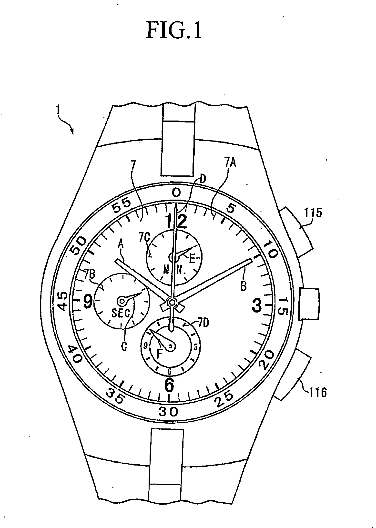
[0031] In FIG. 1, the multifunction timepiece 1 includes an hour hand (basic timepiece pointer) A, minute hand (basic timepiece pointer) B, and second hand (basic timepiece pointer) C for displaying the standard time, and a second CG hand (secondary time information pointer) D, minute CG hand E, and hour CG hand F for displaying CG time, which is information other than the standard time.

[0032] The hour hand A, minute hand B, and second hand C rotate around the center of the dial 7, and point to gradu...


PUM


Abstract

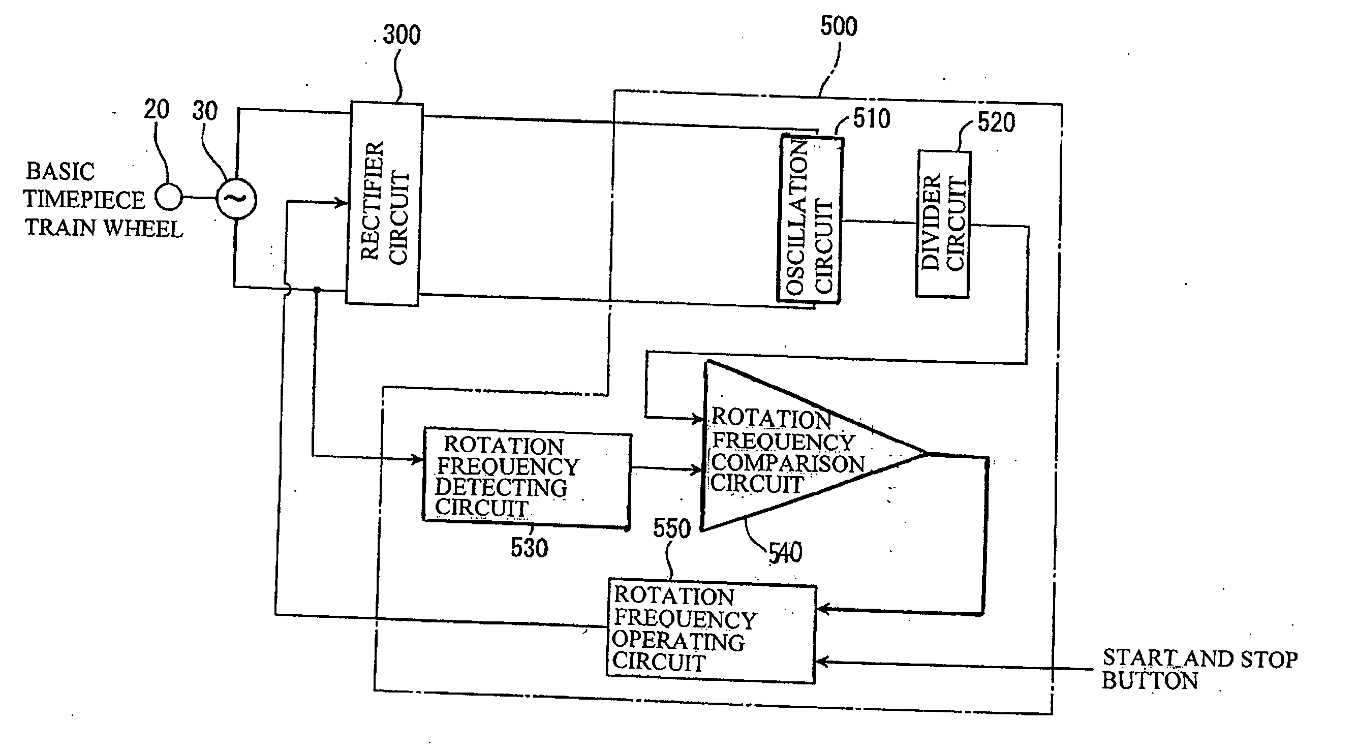
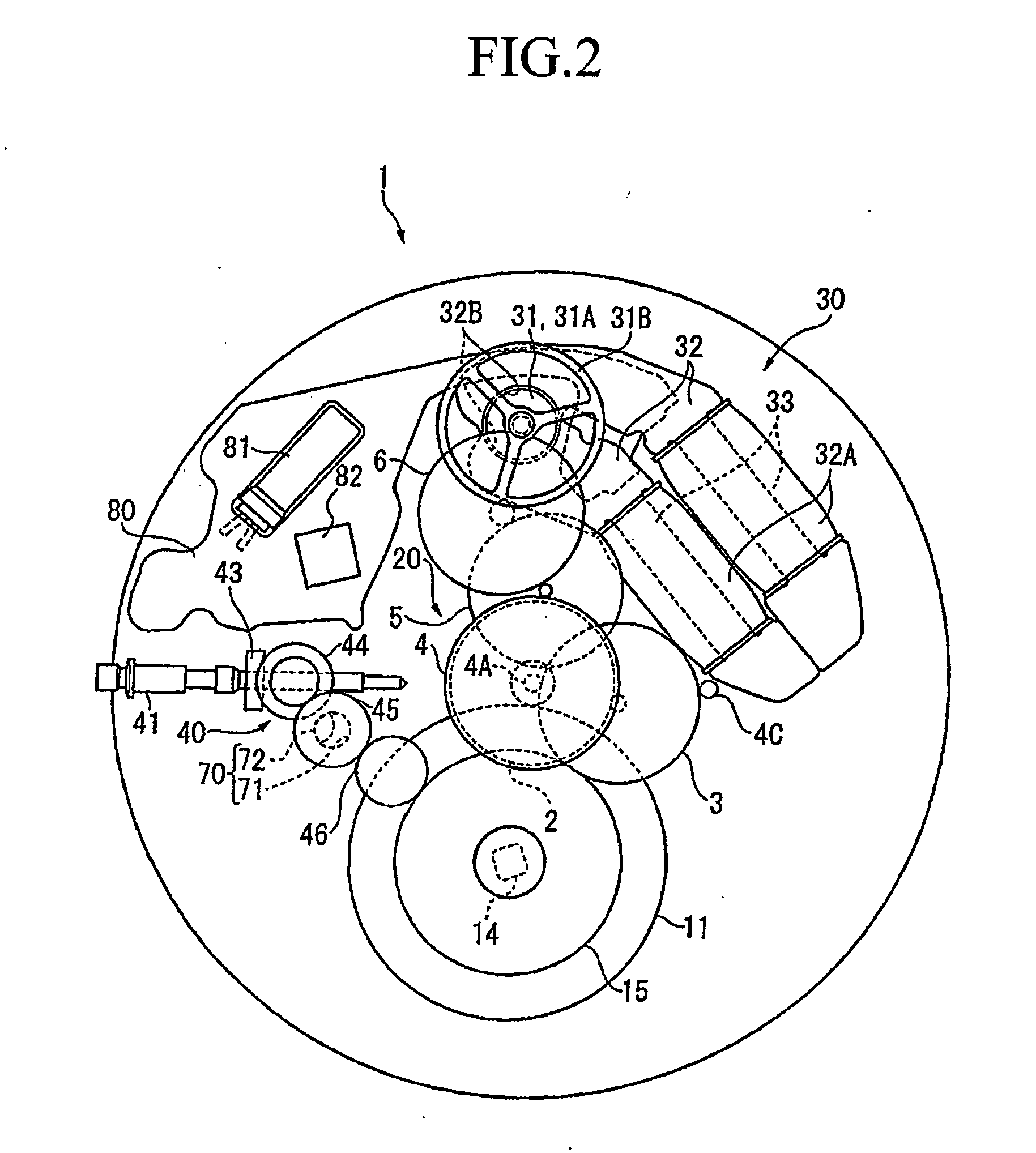
A timepiece having basic timepiece pointers, chronograph information pointers, a mechanical energy storage section, a train wheel, a power generator, and a control section. The basic timepiece pointers are rotated to indicate the standard time. The chronograph information pointers are rotated to indicate chronograph information. The mechanical energy storage section includes a mainspring. The train wheel is disposed between the mechanical energy storage section and the pointers, and transmits energy from the mechanical energy storage section to the pointers. The power generator has a rotating rotor connected to the train wheel, and generates electric power upon receiving the energy from the mechanical energy storage section. The control section is energized by the electric power produced by the power generator, and controls the rotation cycle of the rotor.

Description

BACKGROUND OF THE INVENTION [0001] 1. Field of the Invention [0002] The present invention relates to a stopwatch and a timepiece including a chronograph function. [0003] 2. Description of the Related Art [0004] Multifunction timepieces that include pointers for a chronograph, an alarm, or the like in addition to an hour hand, minute hand, second hand, and other such basic timepiece pointers for indicating the standard time are known in conventional practice as mechanical timepieces with a mainspring drive. [0005] In such multifunction timepieces, the seconds chronograph hand (“chronograph” is hereinafter abbreviated as “CG”) disposed in the middle of the dial, for example, is mounted on a second CG wheel concentric with a seconds wheel and pinion, and is continually driven by the seconds wheel and pinion via a reversing mechanism with detachable gears configured from a reversing plate, a reversing ring, a chronograph coupling lever, and the like (for example, Japanese Laid-Open Pate...

Claims


Application Information

Patent Timeline
IPC IPC(8): G04C10/00G04F7/08G04F8/00
CPCG04C10/00G04F7/0804G04F8/00G04F7/0842G04F7/0833
Inventor HIRAYA, EIICHI
Owner SEIKO EPSON CORP
Learn More