
Devices based on optical waveguides with adjustable bragg gratings

a technology of bragg gratings and optical waveguides, which is applied in the direction of multiplex communication, instruments, cladded optical fibres, etc., can solve the problem of cumbersome process of replacing wave guide segments

Inactive Publication Date: 2005-02-24
LUNA INNOVATIONS
View PDF17 Cites 26 Cited by
  • Summary
  • Abstract
  • Description
  • Claims
  • Application Information

AI Technical Summary

Benefits of technology

39. A method of transfering a light signal from a first polarization maintaining fiber to a second polarization maintaining fiber comprising coupling the first polarization maintaining fiber to the second polarization maintaining fiber at a joint to form a combination polarization maintaining fiber; position a periodic grating to induce mode coupling of one frequency of light in the combination polarization maintaining fiber; adjusting pressure between the periodic grating and the combination polarization maintaining fiber to couple power between a fast mode and a slow mode of the combination polarization maintaining fiber.
40. A tunable polarizer comprising: a polarization maintaining fiber including a core and a cladding; and a periodic grating coupled to the polarization maintaining fiber to couple a first polarization mode of a first wavelength into the cladding.
41. The tunable apparatus of claim 40 wherein the periodic grating presses against the polarization maintaining fiber to induce a periodic change in a refractive index of the polarization maintaining fiber to couple the first polarization mode of the first wavelength into the cladding.
42.

Problems solved by technology

Replacing wave guide segments is a cumbersome process requiring that each end be properly coupled to the light source and the light receiving device.

Method used


Image

  • Devices based on optical waveguides with adjustable bragg gratings
  • Devices based on optical waveguides with adjustable bragg gratings
  • Devices based on optical waveguides with adjustable bragg gratings

Examples


Embodiment Construction

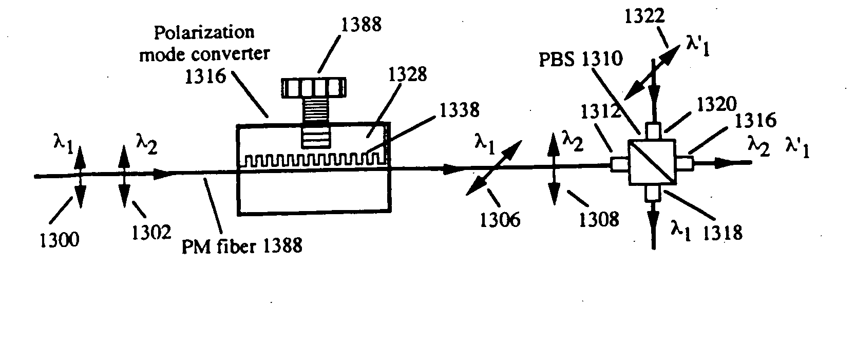
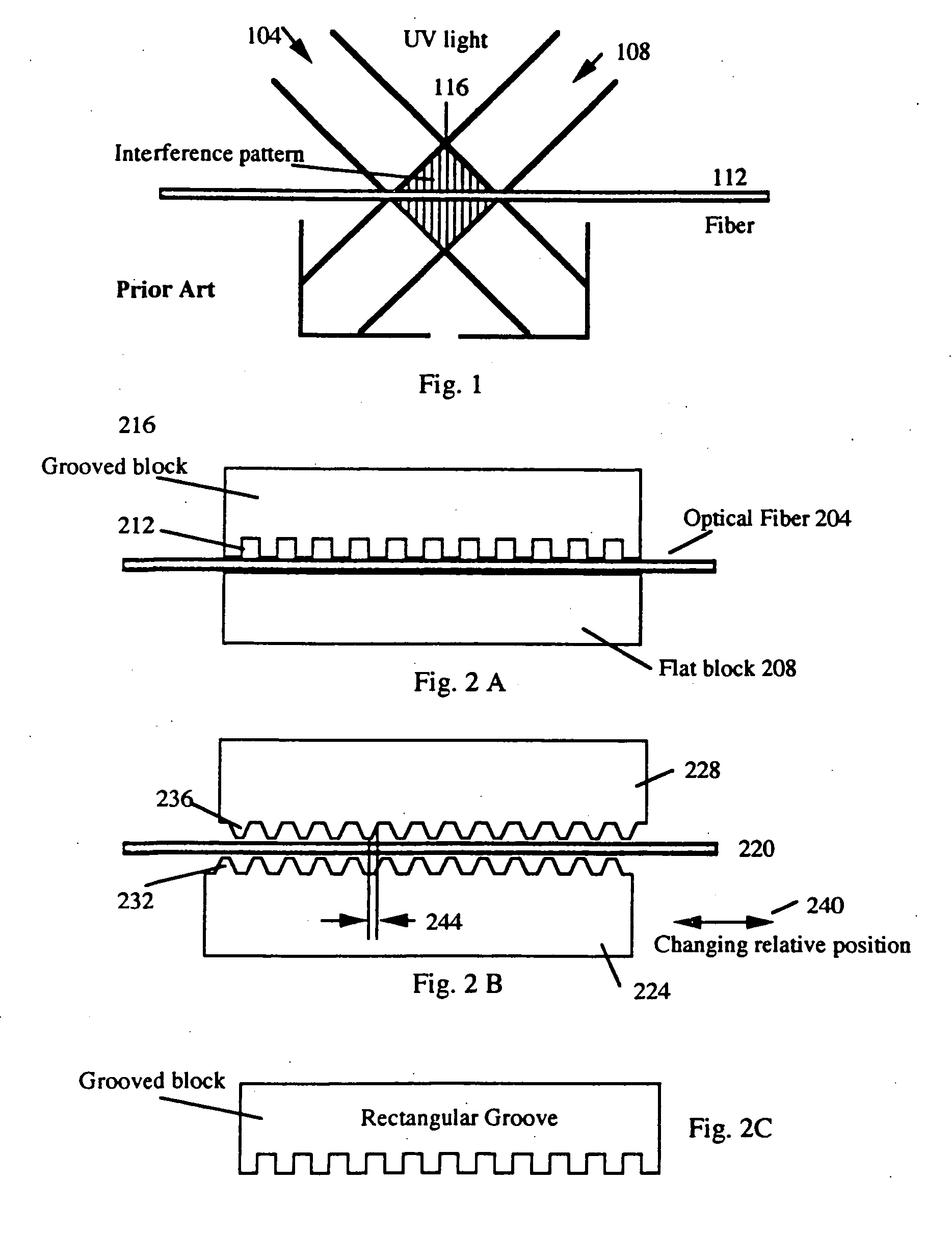
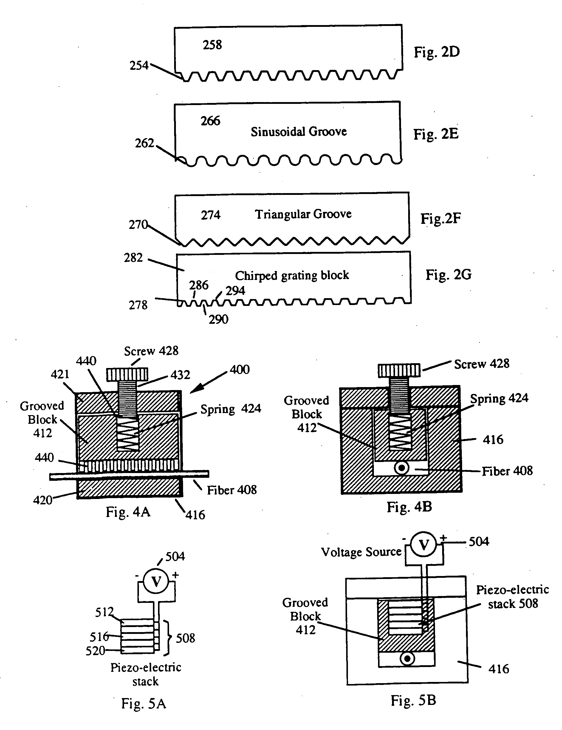
The following invention describes a method and apparatus of using an external grating to cause mode coupling in a wave guide. In the following invention, a number of terms will be used which are herein defined. A wave guide holder as used in this application is any device which holds a wave guide such that relative position, distance, or pressure between the waveguide and a periodic grating can be adjusted. In one embodiment, the waveguide holder holds the waveguide in a fixed position while the position of the external grating is adjusted. In an alternative embodiment, the waveguide holder is adjusted to move the waveguide to different positions with respect to the external grating. Examples of wave guide holders includes, but is not limited to, a block, a substrate of a semiconductor wave guide, the insulation surrounding a wave guide, or other apparatus which can be used to grip or prevent unwanted movement of the wave guide relative to a periodic grating. Furthermore, although ...


PUM


Abstract

A system for filtering light propagating in a waveguide is described. The system utilizes an adjustable periodic grating which induces mode coupling of predetermined frequencies of light propagating in the waveguide.

Description

BACKGROUND OF THE INVENTION 1. Field of the Invention The present invention relates generally to controlling light propagating in a wave guide. More particularly, the present invention relates to using gratings to cause mode coupling of light propagating in a wave guide. 2. Description of Related Art Devices used in optical systems, such as in fiber optic communication systems and sensing systems, often benefit from the filtering or control of light propagating in a wave guide. Examples of such devices include, but are not limited to, source lasers, optical amplifiers, filters and other integrated-optical components. One method of controlling and filtering light utilizes diffraction gratings. Descriptions of such devices and how they benefit from diffraction gratings are described in T. Erdogan and V. Mizrahi, “Fiber Phase Gratings Reflect Advances in Lightwave Technology,” February 1994 edition of Laser Focus World. There are three techniques typically used to create a diffrac...

Claims


Application Information

Patent Timeline
IPC IPC(8): G02B6/02G02B6/26G02B6/28G02B6/34
CPCG02B6/02047G02B6/02061G02B6/02071G02B6/02195G02B6/266G02B6/29322G02B6/274G02B6/276G02B6/2861G02B6/2932G02B6/2706
Inventor YAO, XIAOTIAN STEVE
Owner LUNA INNOVATIONS
Learn More