Support structure with foldable end cap

a support structure and end cap technology, applied in the direction of girders, instruments, boards, etc., can solve the problems of insufficient applicability, inability to provide significant locking force, and complex assembly and other issues

Inactive Publication Date: 2005-03-03
STYLMARK
View PDF23 Cites 5 Cited by
  • Summary
  • Abstract
  • Description
  • Claims
  • Application Information

AI Technical Summary

Benefits of technology

[0027] A method in accordance with the principles of the present invention includes a method of assembling a foldable truss member. The method including unfolding an end cap. The end cap including a plurality of arm members having first and second ends. The arm members are adjacently connected forming a closed loop. The first end of each arm member is pivotally connected to the second end of each adjacent arm member, each arm member also including an attachment member at first and second ends. The method also including attaching a plurality of wall members each having at least two rece

Problems solved by technology

Although useful in some applications, this approach has deficiencies.
The need for numerous differently configured rigid and rotatable members increases the inventory of parts, thereby

Method used


Image

  • Support structure with foldable end cap
  • Support structure with foldable end cap
  • Support structure with foldable end cap

Examples


Embodiment Construction

[0043] In the following description of the illustrated embodiments, reference is made to the accompanying drawings which form a part hereof, and in which is shown by way of illustration, various embodiments in which the invention may be practiced. It is to be understood that other embodiments may be utilized, and structural and functional changes may be made without departing from the scope of the present invention.

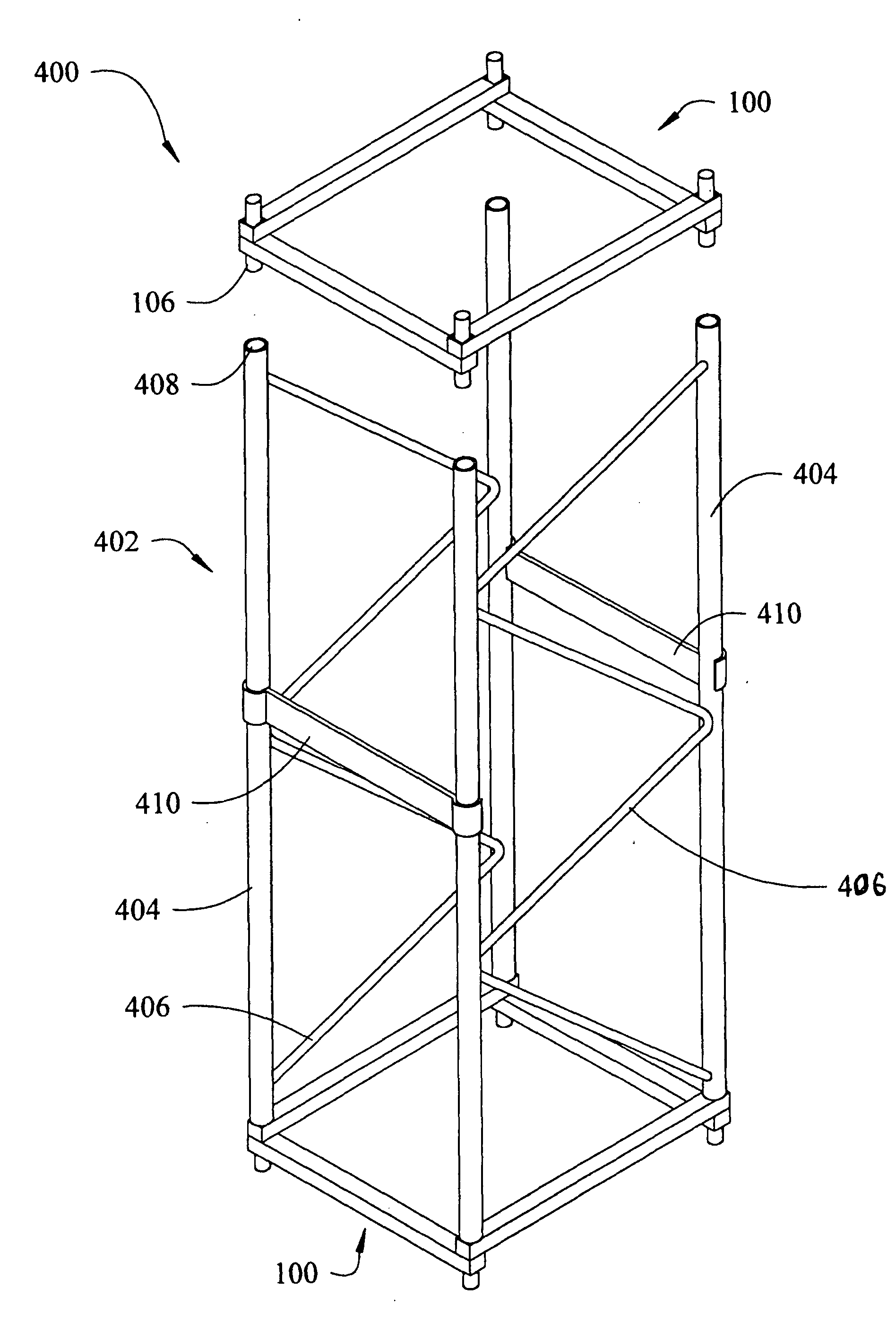
[0044] The present invention provides a portable support structure adapted for use in temporary or permanent stands or displays. The portable truss assembly is provided with a foldable end cap that connects planar wall elements.

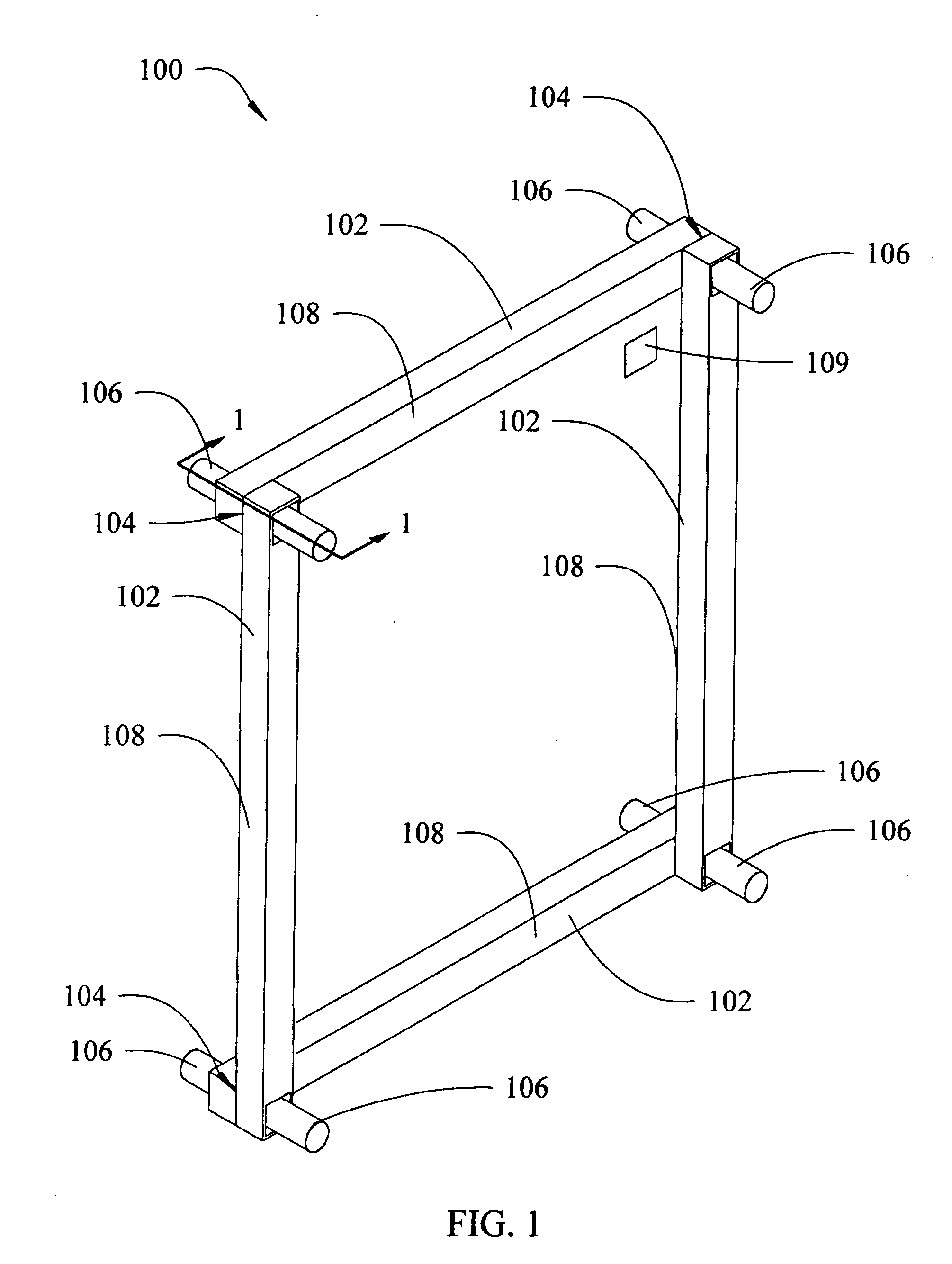
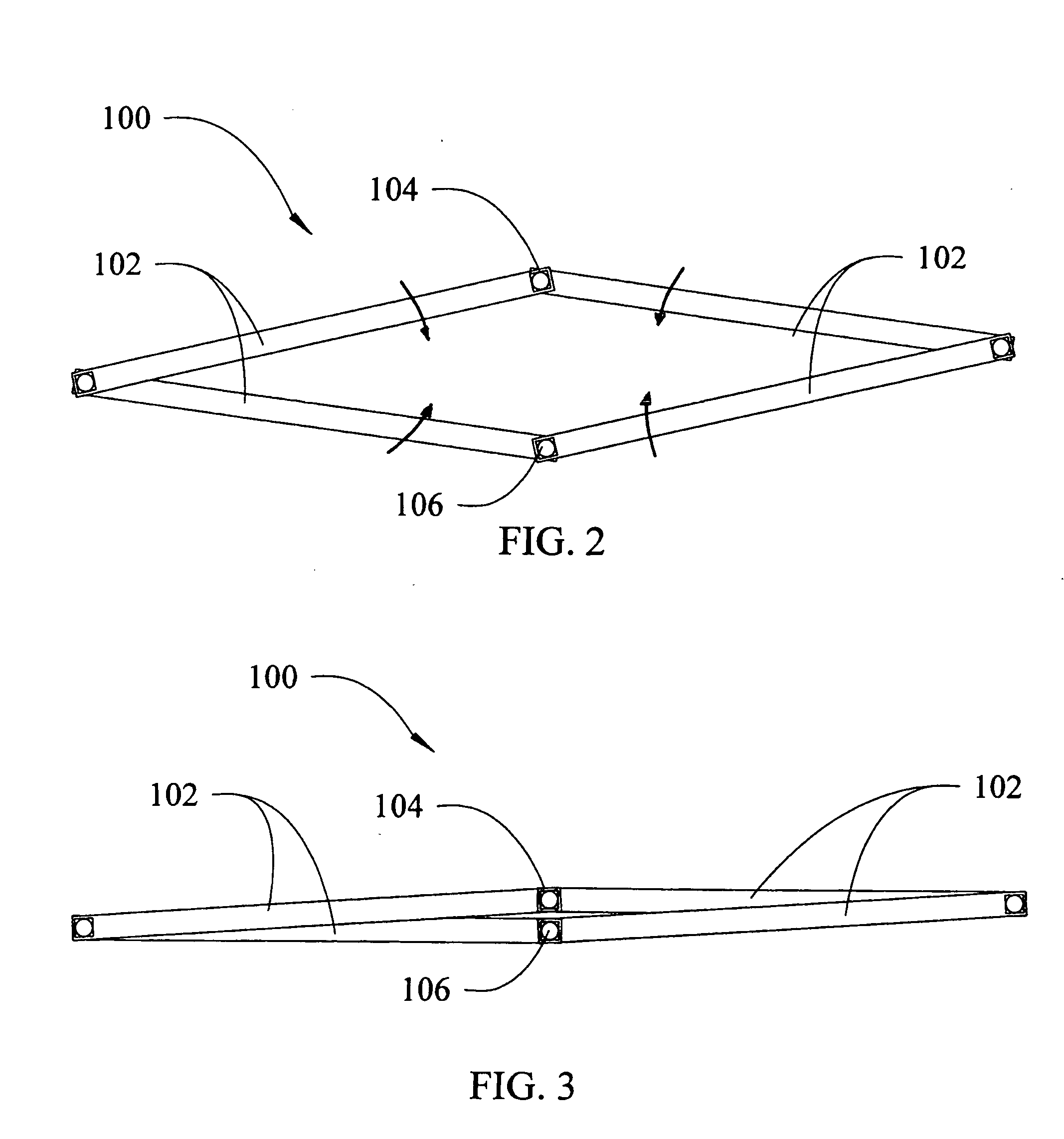
[0045]FIG. 1 illustrates a perspective view of a foldable end cap according to an embodiment of the present invention. In FIG. 1, a foldable end cap 100 includes a plurality of elongated arm members 102. The arm members 102 are adjacently connected such that a first end of a first arm member 102 is pivotally connected to a second end of a second ...


PUM


Abstract

Disclosed herein is a foldable truss assembly for commercial displays. The truss assembly includes a foldable end cap having a plurality of adjacently connected arm members. The arm members are pivotally connected at each end to an adjacent arm member to form a closed loop. The end cap includes an attachment member disposed at each pivotable connection. A plurality of substantially planar wall members are coupled to the attachment members of the end cap by receiving a portion of the end cap in a receiving opening of the wall members. A pair of pivot bars are connectable to diagonally opposite pivot locations of the end cap to stabilize the truss assembly. The pivot bars include a locking member connectable to the free ends of the pivot bars. The locking member prevents relative longitudinal displacement of the pivot bars and prevents the end caps from folding to stabilize and strengthen the truss assembly.

Description

BACKGROUND OF THE INVENTION [0001] 1. Field of the Invention [0002] The present invention relates to portable support structures for use in temporary or permanent stands or displays, such as trade shows and conventions, and particularly to a portable truss assembly having a foldable end cap connecting planar wall elements. [0003] 2. Description of Related Art [0004] Commercial displays such as those used in trade show booths require strong structures that can be easily transported and configured in a wide variety of forms. Such structures need to be lightweight, portable, and able to be quickly set up and broken down. [0005] Prior display structures have contained folding elements that utilize rigid wall members coupled with rotatable wall members. The rotatable wall members allow the display to collapse. The displays include other pivoting members that serve to lock the assembly into an open position. Although useful in some applications, this approach has deficiencies. The need fo...

Claims


Application Information

Patent Timeline
IPC IPC(8): G09F15/00
CPCG09F15/0068
Inventor SCHIPANI, RALPH L.STRAYER, RICHARD K.BRAUER, MARKBLACK, JAMES G.
Owner STYLMARK
Why Eureka
Try Eureka