
Digital door lock capable of detecting its operation states

a digital door lock and state detection technology, applied in the field of digital door locks, can solve the problems of inability to accurately sense, shorten the life of the electromagnetic door lock, and not to operate appropriately

Inactive Publication Date: 2005-03-03
SHIN JUNG GI YOUN
View PDF19 Cites 74 Cited by
  • Summary
  • Abstract
  • Description
  • Claims
  • Application Information

AI Technical Summary

Benefits of technology

[0014] Therefore, the present invention has been made in view of the above problems, and it is an object of the present invention to provide a digital door lock that detects the rotations of a central gear and a rotator in a non-contact sensing manner, thereby enabling the operation state of the door lock itself to be sensed.
[0015] It is another object of the present invention to provide a digital door lock that senses the open / closed state of a door in a non-contact sensing manner to automatically lock the door, thereby enabling the operation state of the door lock itself to be sensed.

Problems solved by technology

However, for the electromagnetic door lock as aforementioned, there have been problems in that the door opening / closing sensor is in the direct contact with the doorframe, so its protruded portion may be easily broken and thus, it can fail to accurately sense the open / closed state of the door; which prevents the door from being automatically locked.
Moreover, the electromagnetic door lock has additional problems in that the door opening / closing sensor checks in the mechanical fashion whether a central gear and a rotator rotate or not, such that there occur some problems that the sensor does not abut fully against the central gear and rotator or may be broken partially, which causes it not to operate appropriately.
As a result, a life span of the electromagnetic door lock is shortened.

Method used


Image

  • Digital door lock capable of detecting its operation states
  • Digital door lock capable of detecting its operation states
  • Digital door lock capable of detecting its operation states

Examples


Embodiment Construction

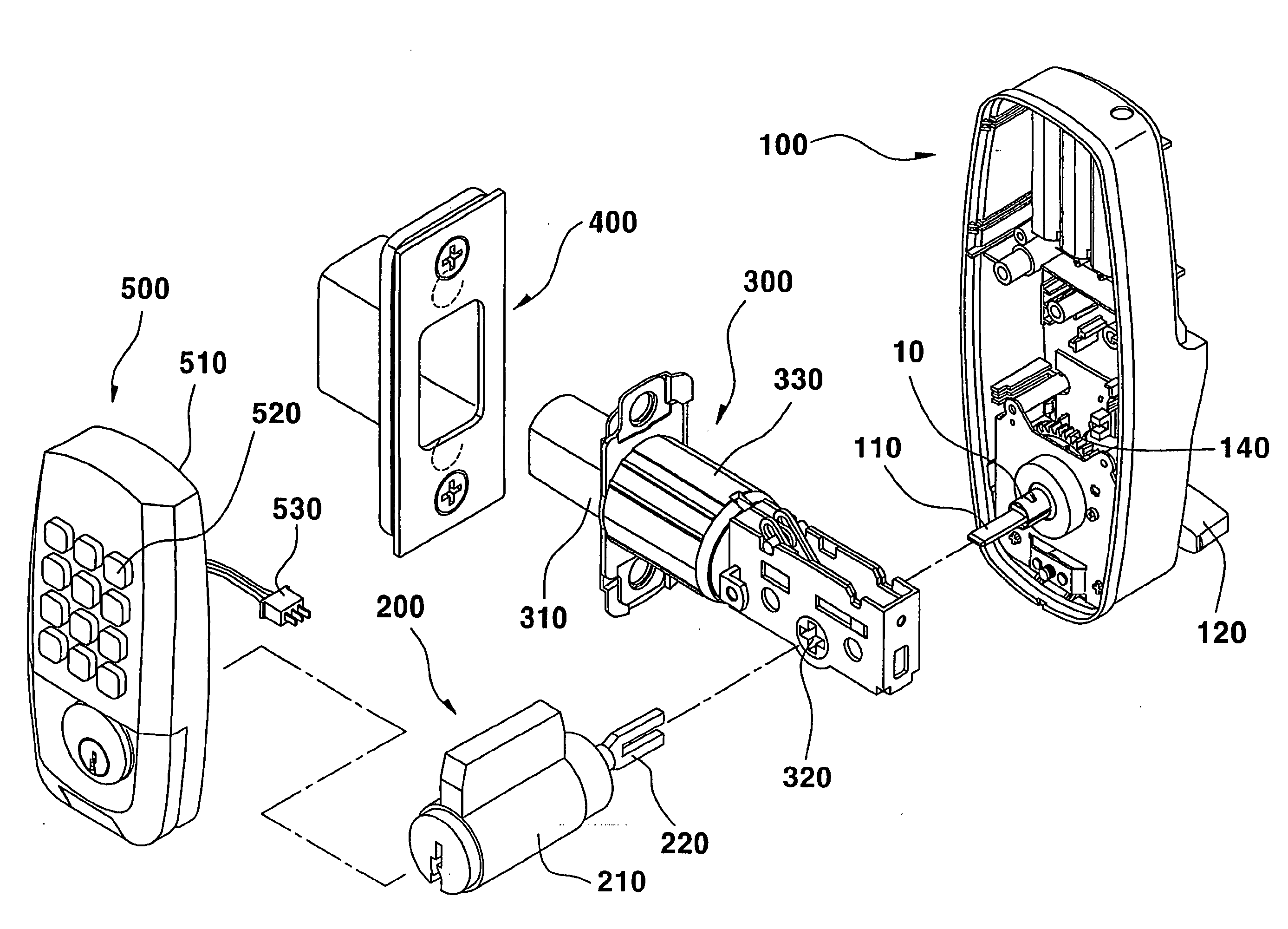
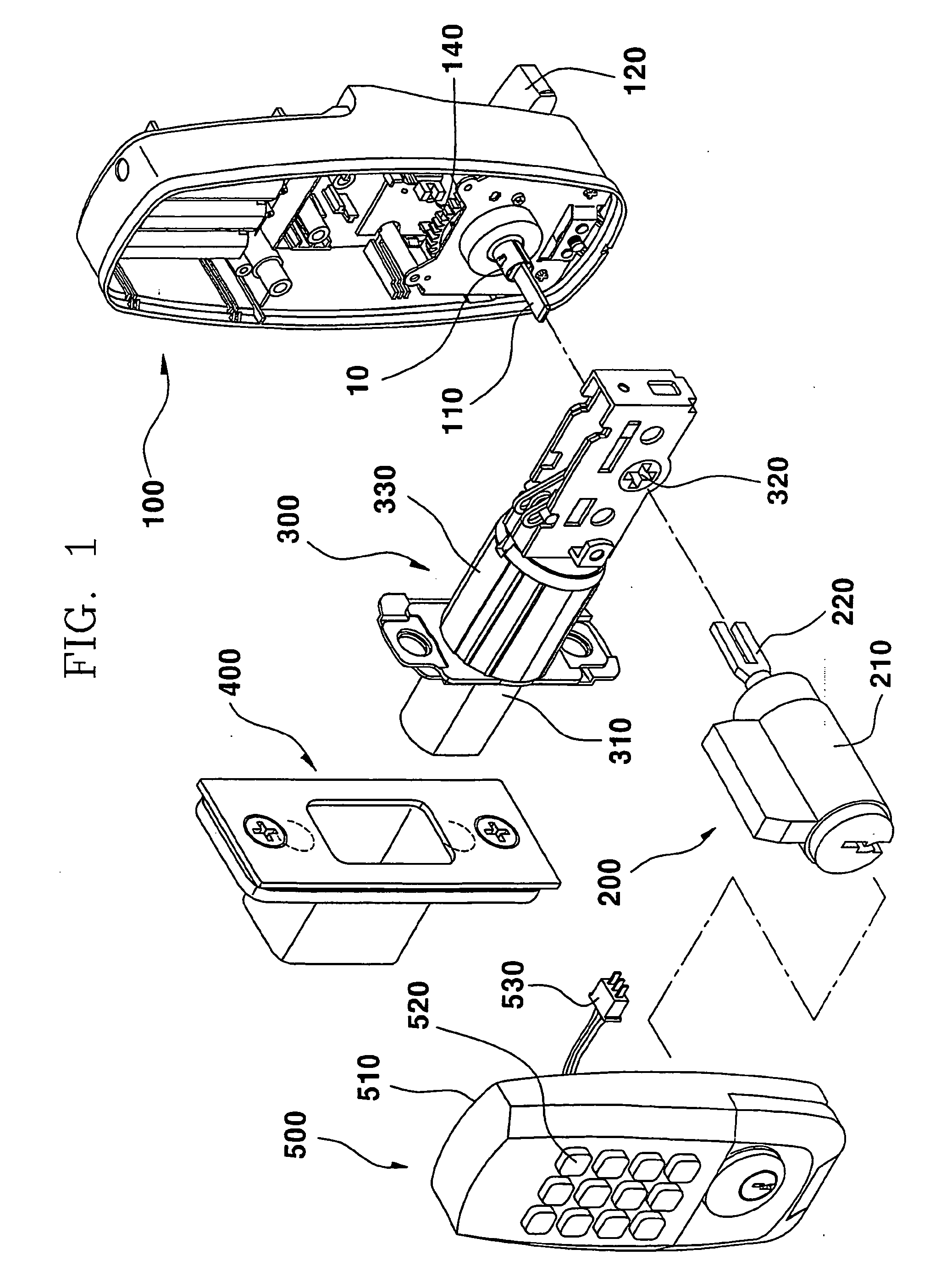
[0026]FIG. 1 illustrates a perspective view of a digital door lock for sensing the operation state of the door lock itself according to the present invention.

[0027] Referring to FIG. 1, the digital door lock includes an inside body 100 installed on a door facing the indoors, a manual key part 200 installed on the door facing the outdoors, a numeric key input part 500 that is formed integrally with the manual key part 200 and has a plurality of numeric keys arranged thereon in the form of a matrix, and a dead bolt assembly 300 that is adapted to lock and unlock the door. The digital door lock further includes a strike box assembly 400 that is installed on a doorframe to correspond to the dead bolt assembly 300.

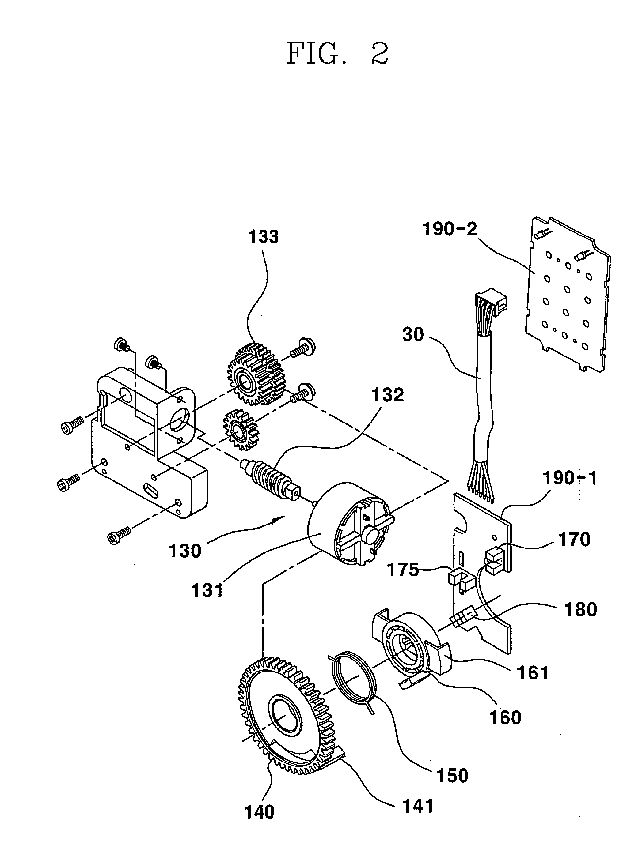
[0028] As shown in FIGS. 1 and 2, the inside body 100 includes a tail piece 110 adapted to rotate according to a mechanical movement of a manipulation button and a central gear 140 adapted to make the tail piece 110 rotate by means of an electric motor.

[0029] As shown in FIG...


PUM


Abstract

The present invention relates to a digital door lock that is capable of detecting the rotations of a central gear and rotator in a non-contact sensing manner so as to accurately sense the locations where the central gear and rotator just rotate, and automatically sensing the opened / closed state of a door to check the operation state of the door lock itself by mounting a receiving sensor on a dead bolt assembly constituting an electromagnetic door lock device and a transmitting sensor on a strike box also constituting the electromagnetic door lock device, thereby lengthening a life span of the door lock.

Description

TECHNICAL FIELD [0001] The present invention relates to a digital door lock, and more particularly, to a digital door lock that is capable of detecting the rotations of a central gear and a rotator in a non-contact sensing manner so as to accurately sense the locations where the central gear and rotator just rotate, and automatically sensing the opened / closed state of a door to check the operation state of the door lock itself by mounting a receiving sensor on a dead bolt assembly constituting an electromagnetic door lock device and a transmitting sensor on a strike box also constituting the electromagnetic door lock device. BACKGROUND ART [0002] An electromagnetic door lock refers to a device that is used to keep a door in an opened / closed state by depressing a combination of prescribed numeric keys on a keypad arranged in the form of a matrix, without using a separate key. Demands for the device have been increasing day by day because of its convenience and reliability in use. [00...

Claims


Application Information

Patent Timeline
IPC IPC(8): E05B47/00G07C9/00G08B13/06
CPCE05B47/0012E05B2047/002E05B2047/0031E05B2047/0069G08B13/06E05B2047/0091G07C9/00674G07C9/00904E05B2047/0084Y10T70/8027Y10T70/7057
Inventor MIN, BYONG DO
Owner SHIN JUNG GI YOUN
Learn More