Glasses type display and controlling method thereof

a technology of glasses and display, applied in the direction of electric controllers, instruments, high-level techniques, etc., can solve the problems of obstructing the view of the user for the outside, difficult that glasses type display is used for the mobile communication terminal, and affecting the user's experience, so as to reduce power consumption, prevent error operation, and facilitate user operation

Active Publication Date: 2006-10-17
NEC CORP
View PDF10 Cites 101 Cited by
  • Summary
  • Abstract
  • Description
  • Claims
  • Application Information

AI Technical Summary

Benefits of technology

[0013]It is therefore an object of the present invention to provide a glasses type display and a glasses type display controlling method, in which t

Problems solved by technology

However, the mobile communication terminal must be small sized, consequently, it has been difficult that a large sized and high quality liquid crystal display is used for the mobile communication terminal.
However, the glasses type display is still large for the display of the mobile communication terminal and obstructs the view of the user for the outside.
Consequently, it is difficult that the glasses type display is used for the mobile communication terminal.
However, at this time, when the user must push some buttons, the call may be disconnected.
In order to solve this problem, when the glasses type display is worked fully by keeping it in the on state, the battery may be consumed soon.
However, this apparatus turns off the power when the device does not detect light reflected from the eyes for a long period of time such as dozes of the user.
However, at a system in which a glasses type display is used at a mobile communication terminal, the size of the mobi

Method used


Image

  • Glasses type display and controlling method thereof
  • Glasses type display and controlling method thereof
  • Glasses type display and controlling method thereof

Examples


first embodiment

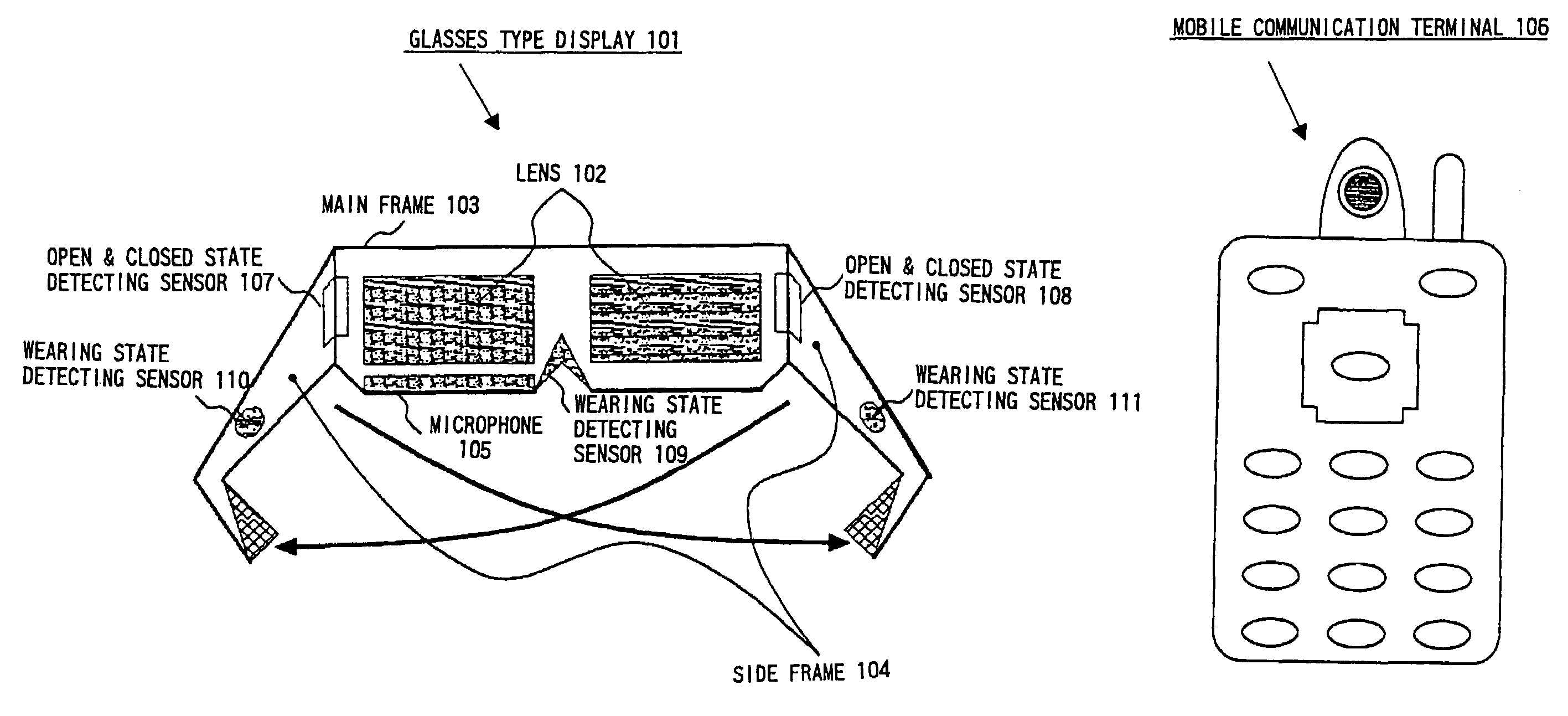
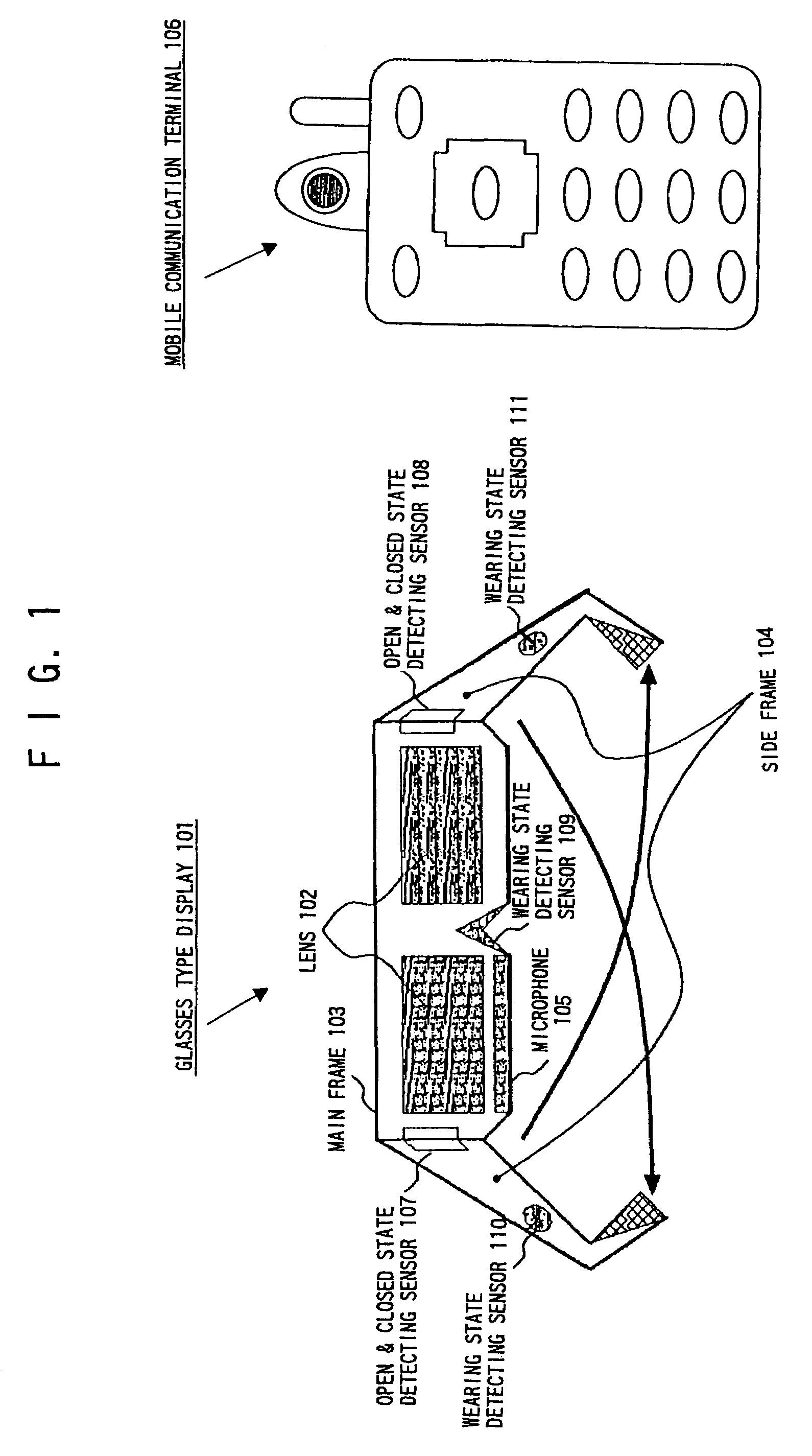
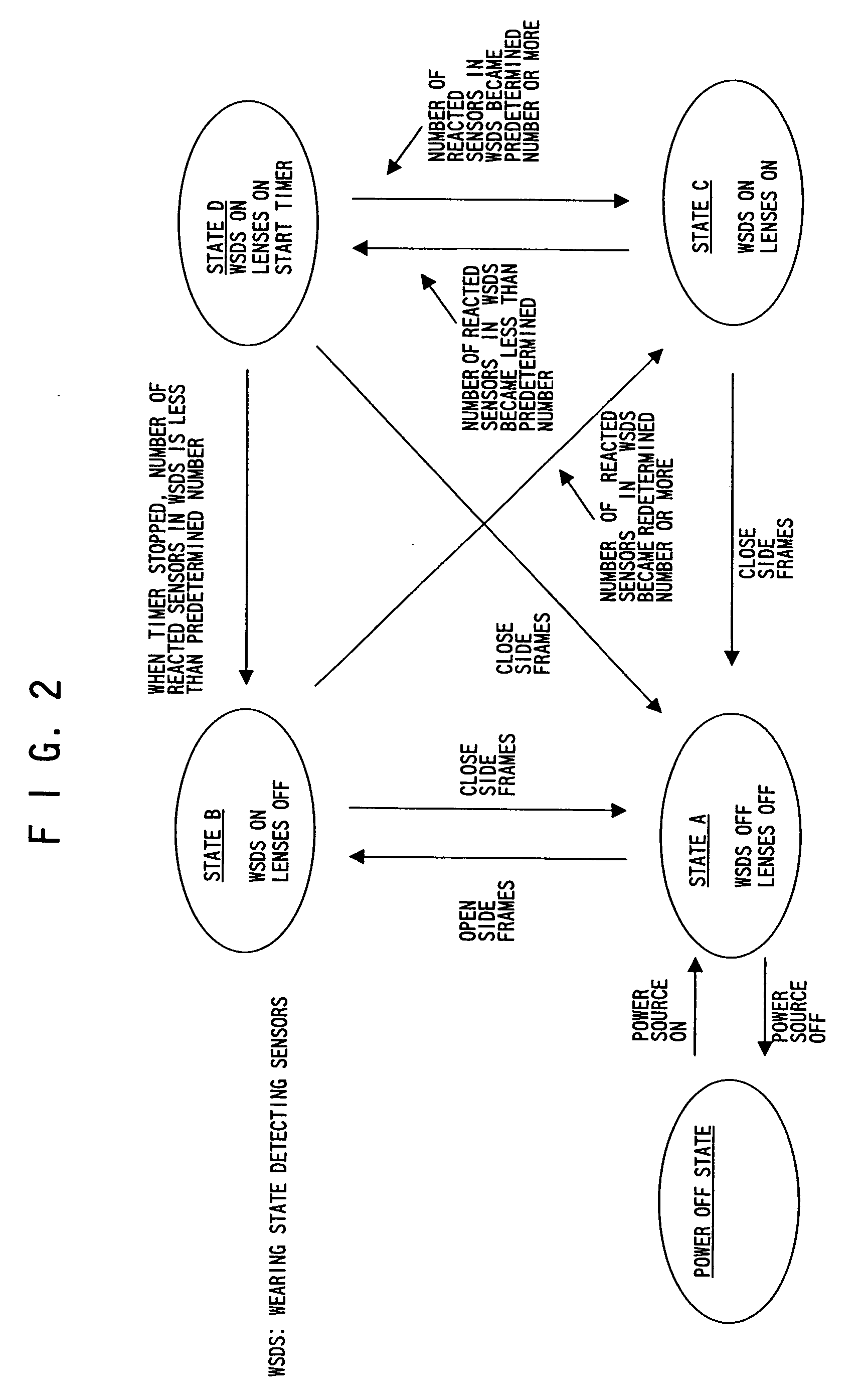
[0100]FIG. 4 is a sequence chart showing the first operation sequence at the present invention. This first operation sequence shows the operation from turning on the power source 302 by the user to starting up the open and closed state detecting sensors 309 and 310. That is, this operation sequence signifies the operation from the power off state to the state A shown in FIG. 2.

[0101]First, the power source 302 is turned on by the user operation on the operation buttons 301, and the power supply is started. And also a starting up signal is sent to the central controller 303 by the user operation on the operation buttons 301, and the central controller 303 is started up. The central controller 303 sends a starting up signal to the received and transmitting signal controller 304, and the received and transmitting signal controller 304 is started up. The central controller 303 also sends a starting up signal to the open and closed state detecting sensors 309 and 310 disposed at the hing...

second embodiment

[0118]FIG. 11 is a sequence chart showing the operation sequence at the present invention. As shown in FIG. 11, first, the received and transmitting signal controller 304 receives a control signal being power off signal from the mobile communication terminal 106 via the antenna, and sends this control signal to the central controller 303. The central controller 303 stops the open and closed state detecting sensors 309 and 310 by sending a stopping control signal to the open and closed state detecting sensors 309 and 310. And the central controller 303 stops the received and transmitting signal controller 304 by sending a stopping control signal to the received and transmitting signal controller 304. After this, the central controller 303 sends a stopping control signal to the power source 302, and the central controller 303 stops itself. The power source 302 that received the stopping control signal from the central controller 303 stops itself after a given amount of time.

[0119]Next...

third embodiment

[0120]FIG. 12 is a sequence chart showing the first operation sequence at the present invention. This first operation sequence shows the operation from putting on the glasses type display 101 by the user to turning on the lenses 306, the speaker(s) 307, and the microphone 308. As shown in FIG. 12, when the user put on the glasses type display 101, the received and transmitting signal controller 304 sends a control signal to the central controller 303. The central controller 303 sends a control signal for starting up the audio and video input and output data controller 305 and making the lenses 306 turn on to the audio and video input and output data controller 305. At this time, the central controller 303 also outputs a control signal for making the audio input and output sections turn on.

[0121]The audio and video input and output data controller 305 sends a control signal for making the lenses 306 turn on to the lenses 306 with video data such as images and a menu screen image, and...


PUM


Abstract

A glasses type display that is connected to an information communication terminal via a wire line or a wireless line, in which the operation by the user is made simple by preventing error operation and the power consumption is decreased by not consuming the unnecessary power, is provided. The glasses type display provides lenses, a main frame, side frames, a microphone, a speaker(s), open and closed state detecting sensors, wearing state detecting sensors. When the user opened the side frames, the open and closed state detecting sensors react, and the wearing state detecting sensors become the on state. When the user put on the glasses type display, the lenses automatically become the on state by that the wearing state detecting sensors detected the wearing state. And when the reaction from a part of the wearing state detecting sensors was turned off, caused by some vibration, the lenses are not immediately turned off. Therefore, an error operation is avoided. When the side frames were closed, the lenses were turned off automatically by the operation of the open and closed state detecting sensors. Therefore, the unnecessary power consumption is avoided.

Description

BACKGROUND OF THE INVENTION[0001]The present invention relates to a glasses type display and a controlling method thereof, in which the glasses type display is used with an audio-visual instrument and an information communication instrument, and in which error operation is prevented and operation by the user is simplified and power consumption is decreased by without using the unnecessary power.DESCRIPTION OF THE RELATED ART [0002]Recently, a liquid crystal display using in a mobile communication terminal has been large sized and high quality, and this progress has been remarkable. Some mobile communication terminal provides a liquid crystal display of 2.2 inches in which the number of pixels is over 60 thousands. Furthermore, some mobile communication terminal provides an additional small liquid crystal display on the rear surface of the mobile communication terminal. However, the mobile communication terminal must be small sized, consequently, it has been difficult that a large si...

Claims


Application Information

Patent Timeline
IPC IPC(8): G09G5/00H04M15/00H04N5/225G05B11/01H04N7/173G02B27/02G02B27/01H04M1/05H04M1/60H04M1/7243H04M1/72454H04N5/64
CPCG02B27/017H04M1/05H04M1/6066H04M2250/12H04M1/72547H04M2250/02H04M19/04Y02D30/70H04M1/7243H04M1/72454G06F3/14
Inventor NAKADA, SUGURU
Owner NEC CORP
Why Eureka
Try Eureka