Heavy duty tire

a tire and tire technology, applied in the field of heavy duty tires, can solve problems such as fretting and brake damage, and achieve the effect of reducing the occurrence of deficient molding and improving the durability of beads

Inactive Publication Date: 2005-03-03
SUMITOMO RUBBER IND LTD
View PDF5 Cites 35 Cited by
  • Summary
  • Abstract
  • Description
  • Claims
  • Application Information

AI Technical Summary

Benefits of technology

[0014] Since the present invention is arranged in such a manner, it is possible to further improve the bead durability and to effecti...

Problems solved by technology

There also exists a problem in that the carcass cords scratch against the bead core at ...

Method used


Image

  • Heavy duty tire
  • Heavy duty tire
  • Heavy duty tire

Examples


examples

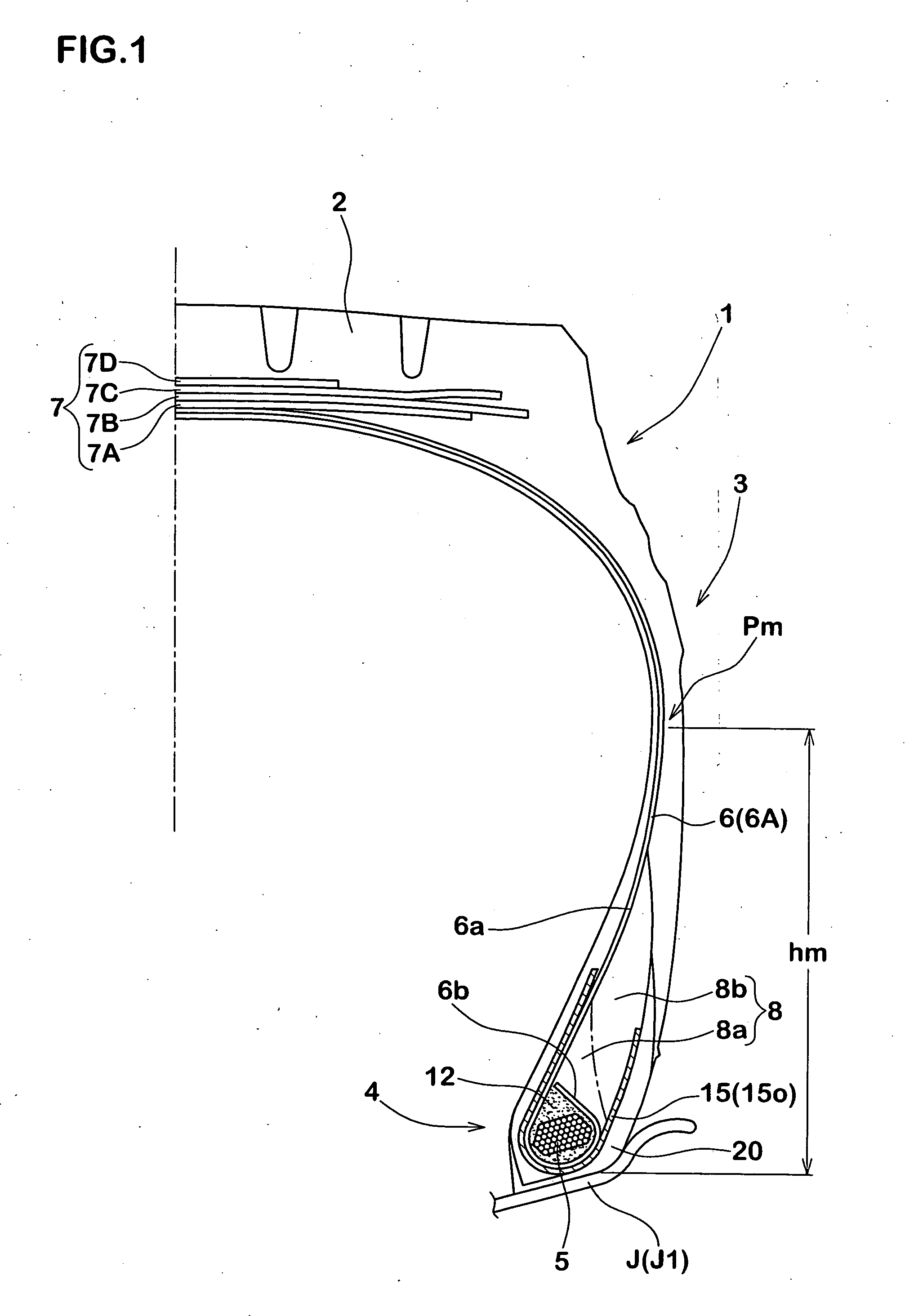
[0061] Radial tires for heavy load use having a tire size of 11R22.5 and having a bead structure as illustrated in FIG. 1 were manufactured by way of trial on the basis of the specifications of Tables 1 to 5, whereupon tests on bead strength, bead durability (general), thermal bead durability, rate of incidence of deficient moldings, and changes over time of the bead base were conducted for the respective sample tires. In this respect, specifications other than those listed in the table were common to all of the tires.

[0062] In this respect, the Comparative Example 1 was of conventional arrangement in which the ply turn-up portion of the carcass is wound up along the outside surface of the bead apex rubber as illustrated in FIG. 6, wherein a height h2 of the ply turn-up portion from the bead base line was 65 mm.

[0063]

[0064] The sample tires were respectively mounted to rims (7.50×22.5), and upon filling water from a valve into the interior of the tire, the destructive water pressu...


PUM


Abstract

It is a subject to restrict occurrence of deficient moldings and to improve the bead durability without harming the advantages provided through a bead wind structure, and for this purpose, a ply turn-up portion of a carcass comprises a winding portion, which continues from a main portion that is bent along a bead core, which extends while being spaced from the bead core, and which inclines at an angle θ that is smaller than 90°. A height of a tip end of the winding portion from an outer surface of the bead core is 3 to 15 mm. A cushion rubber having a complex elastic modulus E1* at 70° C. of 2 to 25 MPa is disposed in a region surrounded by a ply main body portion of the carcass, the bead core and the winding portion.

Description

BACKGROUND OF THE INVENTION [0001] 1. Field of the Invention [0002] The present invention relates to a heavy duty tire of improved bead durability while achieving weight saving. [0003] 2. Description of the Prior Art [0004] Tires for heavy load use are filled with high air pressure and are used under demanding conditions of largely applied load. Bead portions are thus firmly reinforced as illustrated in FIG. 6, having a large thickness and also an extremely large weight. For reducing weights of such tires for heavy load use, it has conventionally been suggested for tires of bead structure (also referred to as bead wind structure) as illustrated in FIG. 7 in which a ply turn-up portion a of a carcass is wound around a bead core b substantially round thereof and in which a tip end portion a1 of the ply turn-up portion a is secured between an outer surface of the bead core b in the radial direction and a bead apex rubber c (see Japanese Patent Laid-Open Publication No. 11-321244(1999) ...

Claims


Application Information

Patent Timeline
IPC IPC(8): B60C15/00B60C15/04B60C15/06
CPCB60C15/0027B60C15/04B60C15/06Y10T152/10828Y10T152/10837Y10T152/10846B60C2015/044B60C15/0607B60C2200/06
Inventor MARUOKA, KIYOTOOHTSUKI, HIROTOSHI
Owner SUMITOMO RUBBER IND LTD
Why Eureka
Try Eureka