
Vehicle exterior material clamping apparatus with scissors-like closure motion

a clamping device and vehicle exterior technology, applied in the direction of load securing, transportation items, transportation and packaging, etc., can solve the problems of not teaching that an actuated clamping device may be mounted onto a truck, cannot be easily adapted for temporary mounting on the exterior of a truck, and cannot be easily adjusted for different sized trucks and workloads, so as to achieve safe transportation

Inactive Publication Date: 2005-03-03
ADAMCZEWSKI ZBIGNIEW JOZEF +1
View PDF18 Cites 2 Cited by
  • Summary
  • Abstract
  • Description
  • Claims
  • Application Information

AI Technical Summary

Benefits of technology

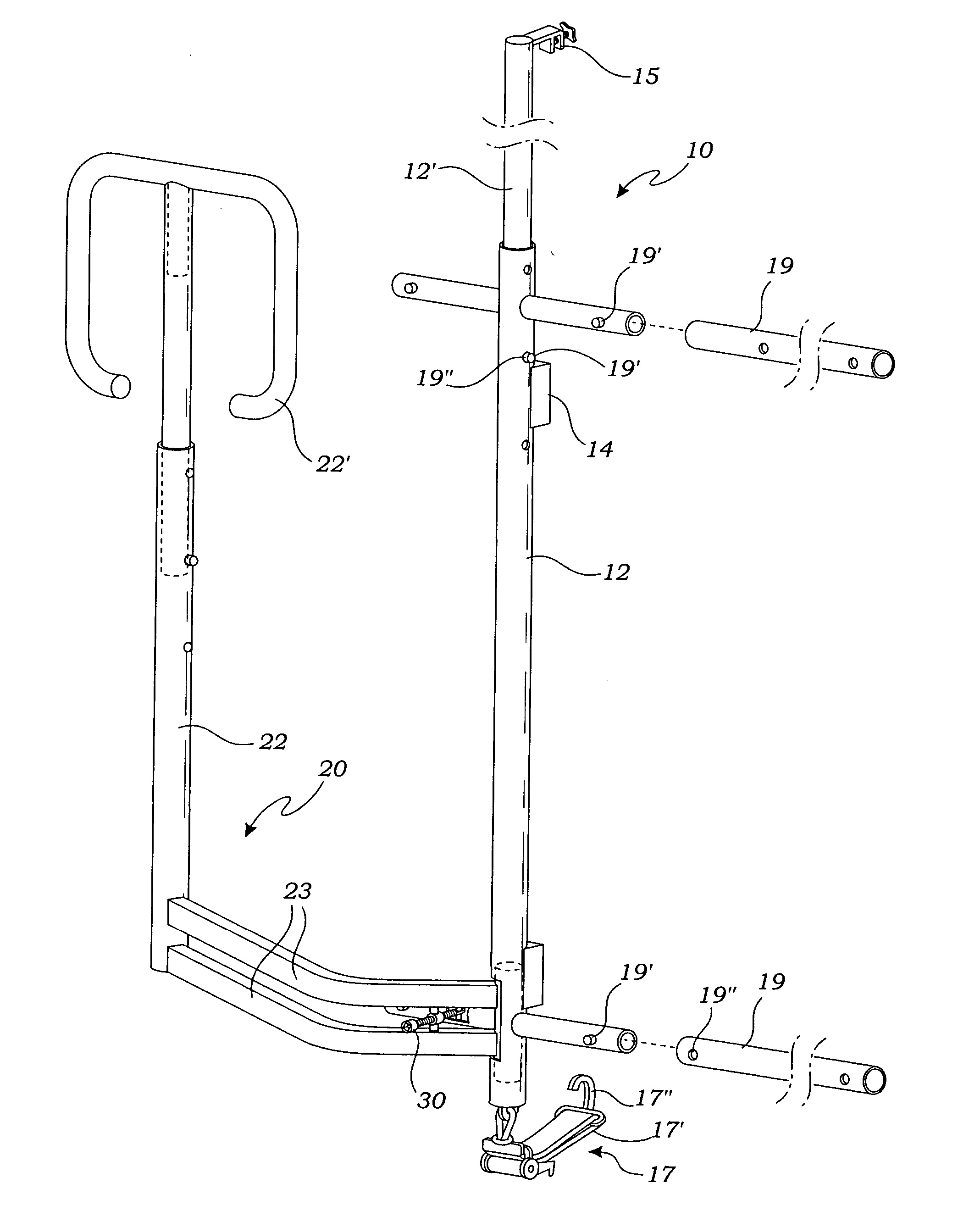
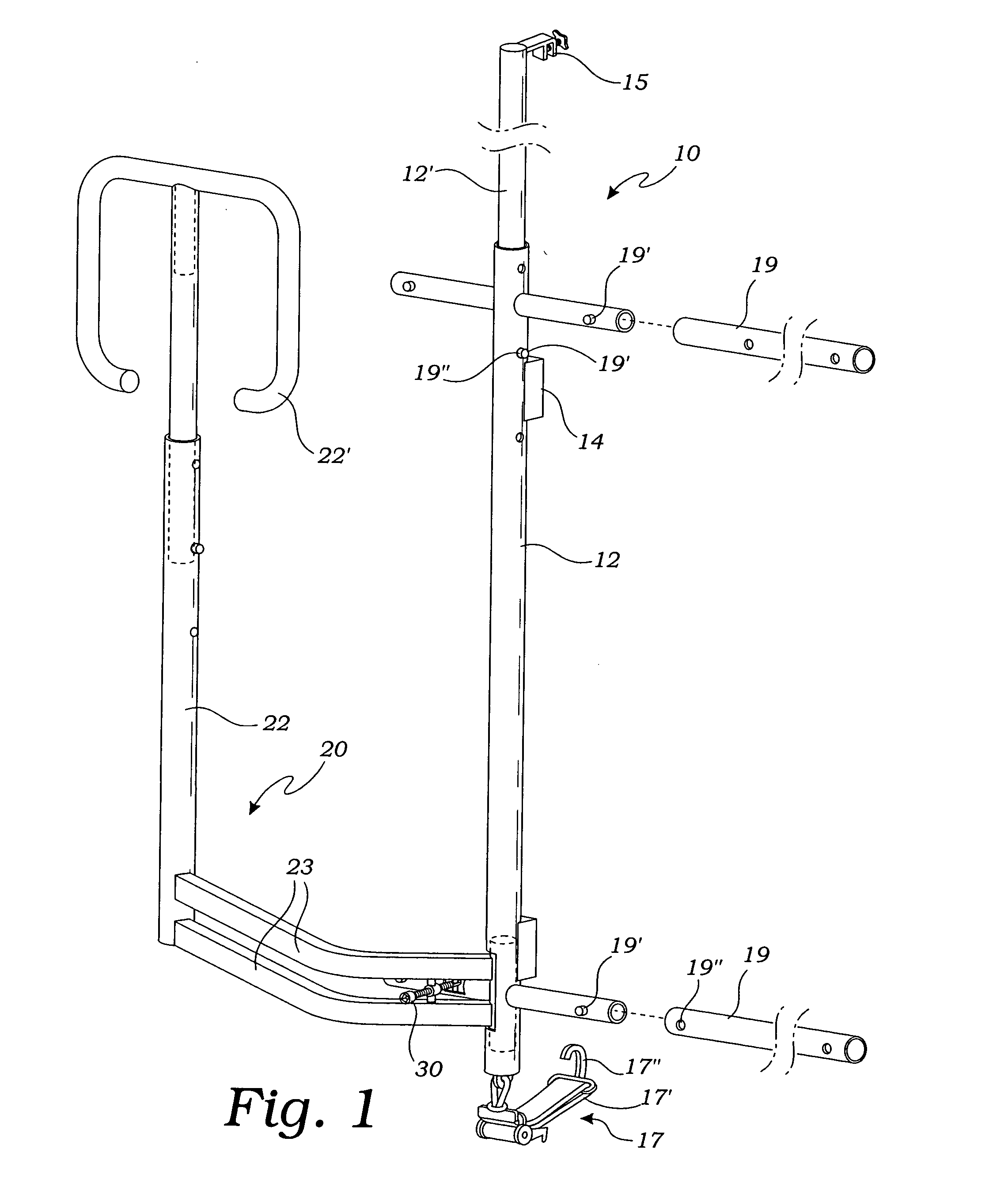
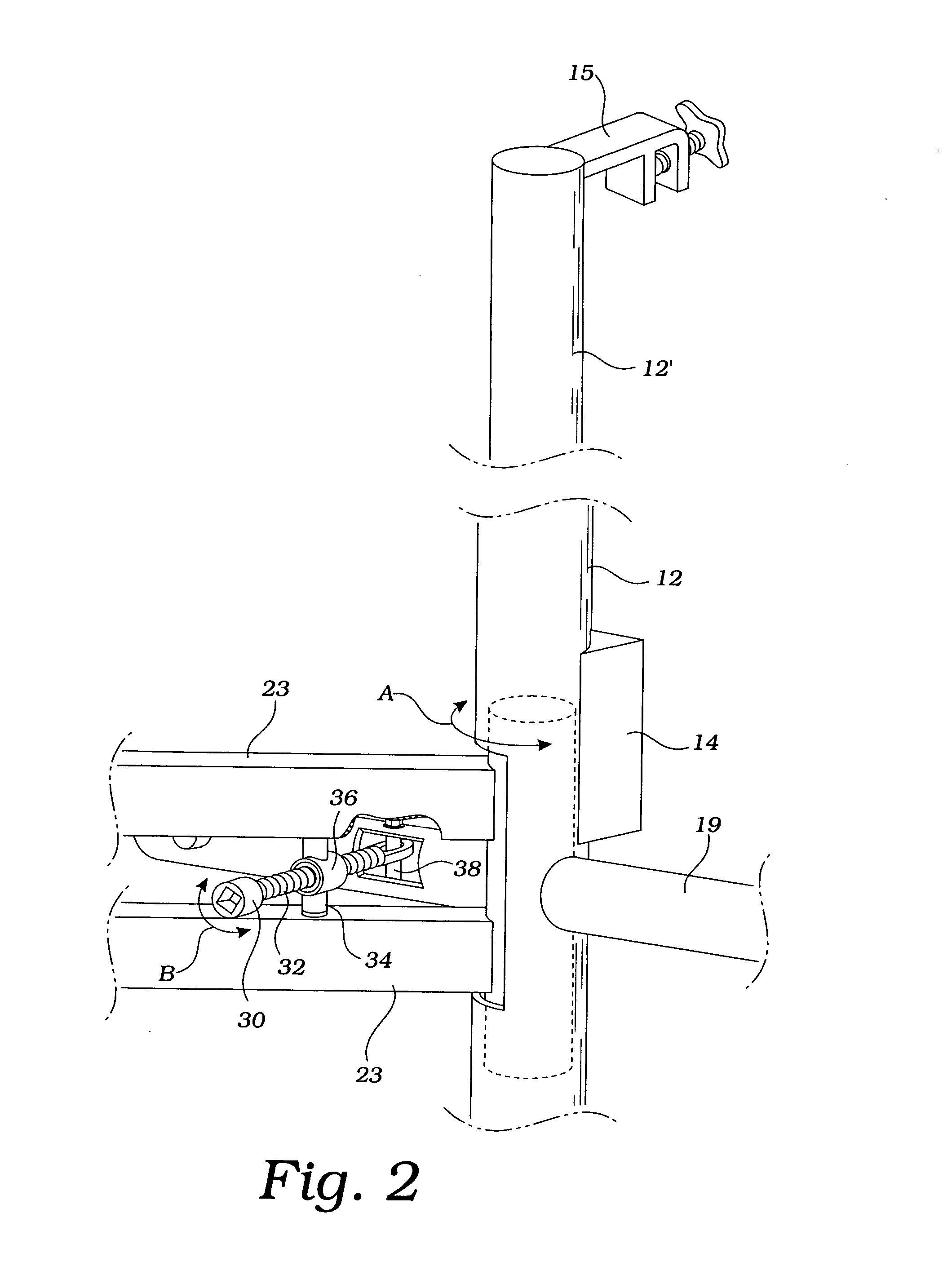
[0014] The present invention provides an apparatus for carrying a workpiece adjacent an exterior surface of a vehicle, including a stationary resting surface mounted on the exterior surface and one or more movable clamping bars positioned adjacent to the resting surface. A driving screw moves the clamping bar in a scissors type motion, alternately toward the resting surface, so as to clamp the workpiece, and away from the resting surface so as to release the workpiece, whereby the workpiece may be safely transported by the vehicle. The apparatus may be mounted onto a panel truck, normally adjacent to one of its side panels, or may be mounted on a side of a pick-up type truck.

Problems solved by technology

However, the '123 reference is not easily adapted for temporary mounting onto the exterior of a truck nor for easy adjustability for different sized trucks and workloads.
This is undesirable in most cases to those that would haul materials on a non-commercial basis.
However, the prior art does not teach that an actuated clamping device may be mounted onto a truck for clamping panel goods for transport.

Method used


Image

  • Vehicle exterior material clamping apparatus with scissors-like closure motion
  • Vehicle exterior material clamping apparatus with scissors-like closure motion
  • Vehicle exterior material clamping apparatus with scissors-like closure motion

Examples


Embodiment Construction

[0028] The above described drawing figures illustrate the present invention, an apparatus for carrying panel materials such as gypsum wallboard, plywood sheets, glass sheets and other materials, which will be summarily referred to herein as the “workpiece 7”, where the workpiece 7 is held in a vertical attitude adjacent to a side or rear panel of a vehicle 5 such as a panel truck, shown in FIGS. 3-6 or a pick-up type truck, shown in FIG. 7. Preferably, the apparatus mounts onto a truck side panel 3 and secures one or more sheets or panels which constitute the workpiece7 so that they may be safely transported.

[0029] The present invention includes a stationary means for resting 10, the resting means mounted on the exterior surface 3 (or panel) of the vehicle 5 wherein the workpiece 7 is rested against the resting means 10. The resting means 10 preferably includes one or more vertical rest bars 12 held in contact with the truck's panel, preferably in a temporary manner by rubber conta...


PUM


Abstract

An apparatus for carrying a workpiece adjacent an exterior surface of a vehicle, provides a stationary resting surface mounted on an exterior surface of the vehicle and one or more movable clamping bars positioned adjacent to the resting surface. A driving screw moves the clamping bar in a scissors type motion, alternately toward the resting surface, so as to clamp the workpiece, and away from the resting surface so as to release the workpiece, whereby the workpiece may be safely transported by the vehicle. The apparatus may be mounted onto a panel truck, normally adjacent to one or both side panels, or may be mounted on the sides of a pick-up type truck.

Description

BACKGROUND OF THE INVENTION [0001] INCORPORATION BY REFERENCE: Applicant(s) hereby incorporate herein by reference, any and all U.S. patents, U.S. patent applications, and other documents and printed matter cited or referred to in this application. [0002] 1. Field of the Invention: [0003] This invention relates generally to materials transporting devices, and more particularly to such a device for clamping panels onto the exterior of a truck for transporting such goods. [0004] 2. Description of Related Art [0005] The following art defines the present state of this field: [0006] Adamczewski et al, U.S. Pat. No. 6,193,123, teaches a precursor apparatus of a similar type to the present invention and intended for the same purpose. However, the '123 reference is not easily adapted for temporary mounting onto the exterior of a truck nor for easy adjustability for different sized trucks and workloads. The '123 reference teaches that the clamping drive be mounted under the truck with the sc...

Claims


Application Information

Patent Timeline
Patent Type & Authority Applications(United States)
IPC IPC(8): B60P3/00B60P7/10B60R9/02
CPCB60P3/002B60R9/02B60P7/10
Inventor ADAMCZEWSKI, ZBIGNIEW JOZEFGOSEY, RUTH ESTHER
Owner ADAMCZEWSKI ZBIGNIEW JOZEF
Learn More