Ultrasonic fog maker and methods of drug delivery and air freshening

a fog maker and ultrasonic technology, applied in air humidification systems, lighting and heating apparatuses, heating types, etc., can solve the problems of large size of cosub>2 /sub>fog generators, inability to easily apply fog quantity, and inability to prevent vacuum from developing, so as to reduce pressure at the outlet. , the effect of preventing the vacuum from developing

Inactive Publication Date: 2005-03-03
PALANTIC TRADING
View PDF16 Cites 17 Cited by
  • Summary
  • Abstract
  • Description
  • Claims
  • Application Information

AI Technical Summary

Benefits of technology

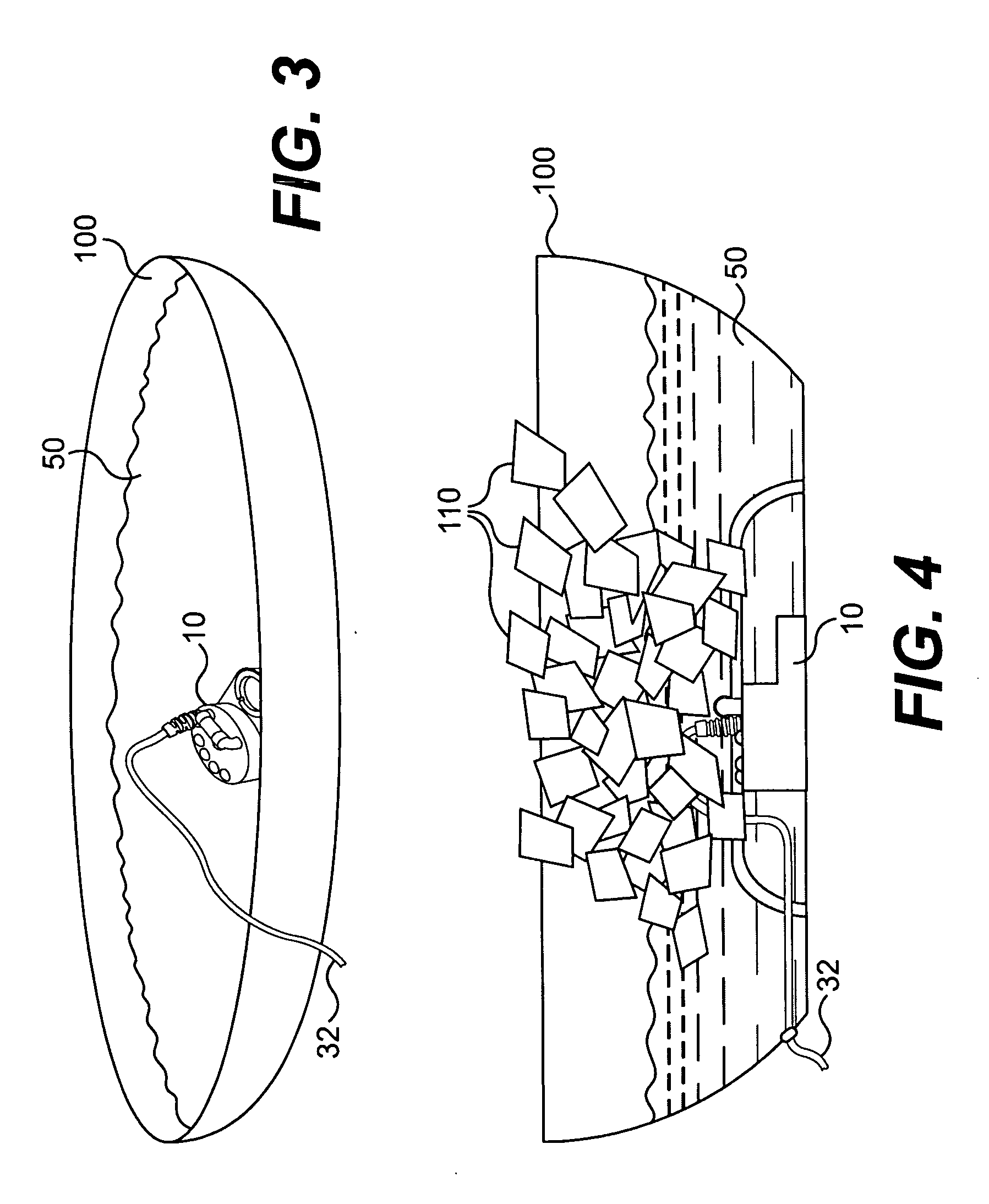
In other further embodiments of the housing, the visually appealing display may include at least one light and a stand adapted to support the housing. Further, the stand may maintain the housing and the liquid source above a surface such that the fog may fall toward the surface after emanating from the liquid source.
In another further embodiment of the device, an air inlet may be provided in the device to prevent a vacuum from developing in the device if the pressure at the outlet is greatly reduced.

Problems solved by technology

One disadvantage of CO2 fog generators is that the fog quantity they produce is unregulated, i.e., the fog quantity cannot be readily applied in any situation without adjusting the size of the of CO2 block as the quantity of fog produced is largely based on the size of the block used.
Further, in applications requiring a large amount of fog, the size of the CO2 fog generator can become large and cumbersome.
Further, when the CO2 block melts, it must be replaced by another costly CO2 block.
Unfortunately, helium bubble generators tend to produce a small quantity of bubbles that may fail to create a dense and realistic fog.
Further, increasing the helium levels in a room may have a negative impact on the comfort of people in the room.
Similar to the CO2 block fog generator, liquid N2 fog generators tend to be large and require a continuous supply of costly of liquid N2.
Further, these fog generators may be hazardous because they require both a boiler to heat the water and extremely cold liquid N2 to operate.
One common fact among the aforementioned fog generators is the creation of fog in a way that fails to be visually pleasing, i.e., the only thing created is fog.
In addition, the fog created serves no purpose other than perhaps being indicative of airflow and simulating fog.

Method used


Image

  • Ultrasonic fog maker and methods of drug delivery and air freshening
  • Ultrasonic fog maker and methods of drug delivery and air freshening
  • Ultrasonic fog maker and methods of drug delivery and air freshening

Examples


Embodiment Construction

Reference will now be made in detail to presently preferred embodiments of the invention, which are illustrated in the drawings. An effort has been made to use the same reference numbers throughout the drawings to refer to the same or like parts.

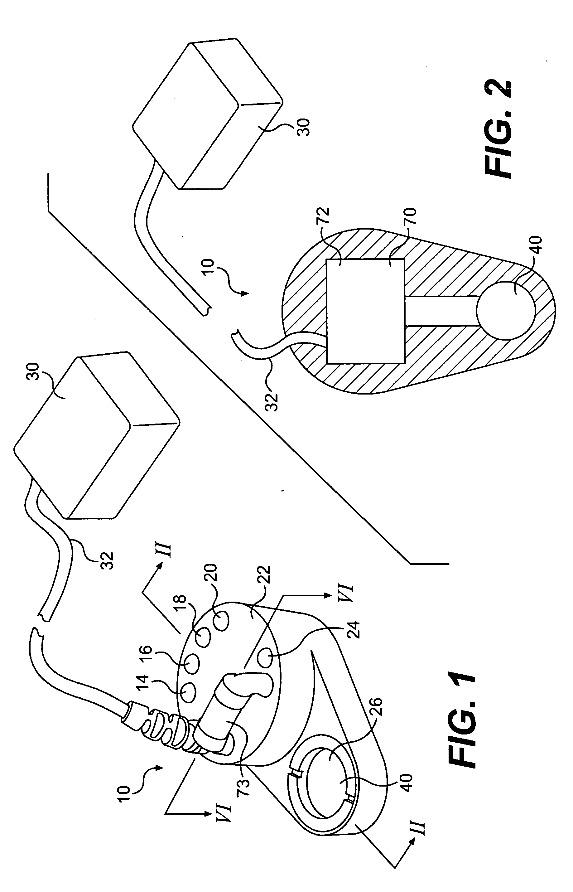
FIG. 1 is a perspective view of a housing 10 for an ultrasonic fog generator. The housing 10, which is preferably sized to be hand-held, has a plurality of lights 14, 16, 18, 20 thereon. Each of the lights 14, 16, 18, 20 is adapted to emit a particular color of light which may be the same as or different than the color emitted by one or more of the other lights 14, 16, 18, 20. In addition, each of the lights 14, 16, 18, 20 may be adapted to change colors during use, i.e., the colors may be variable. Power for the lights 14, 16, 18, 20 is provided by a power source 30 and is delivered to the housing by a power cord 32, as later described in detail.

Also shown on a top side 22 of the housing 10 is an indicator lamp 24, an ultrasound depress...


PUM

PropertyMeasurementUnit
DC voltageaaaaaaaaaa
coloraaaaaaaaaa
colorsaaaaaaaaaa

Abstract

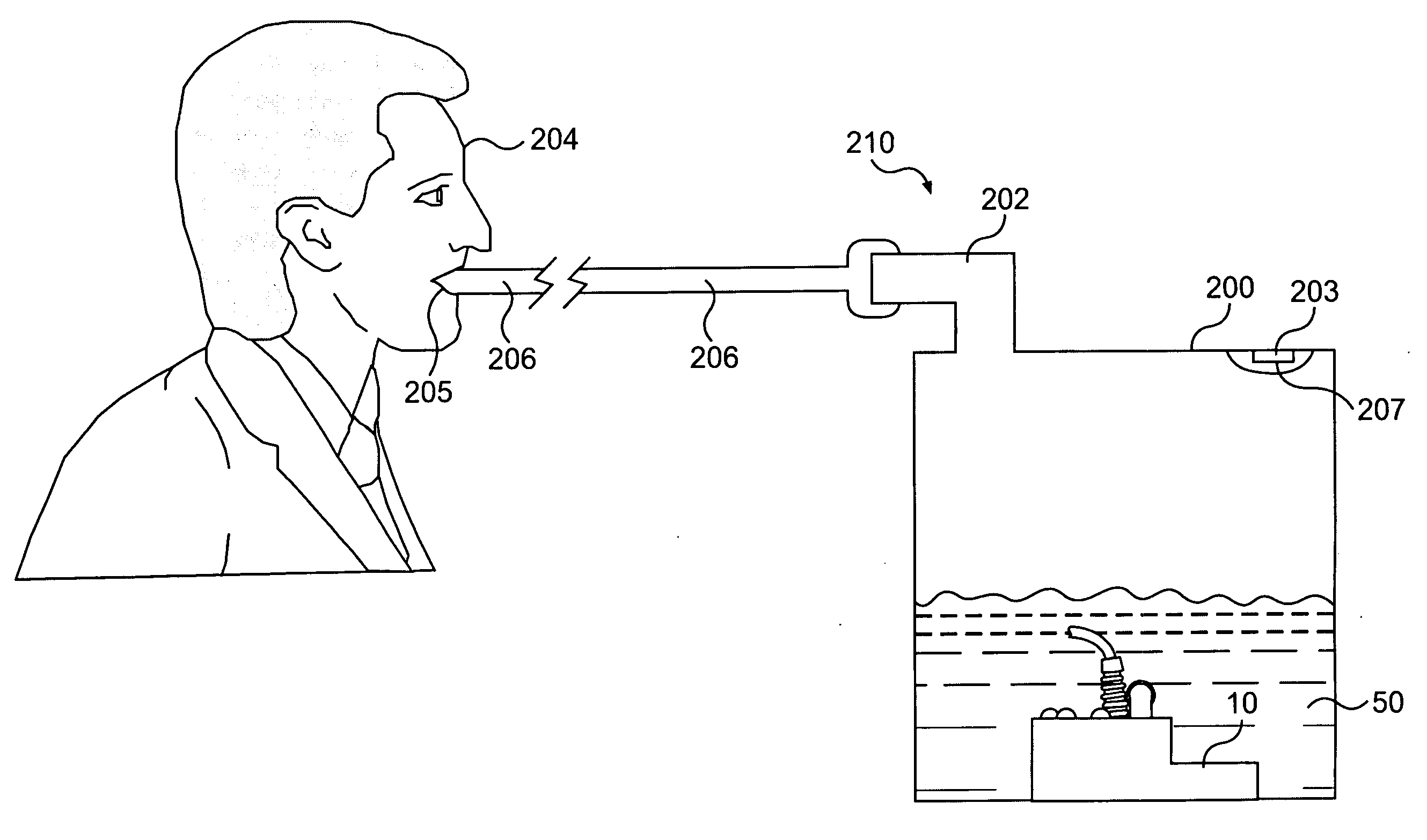
An ultrasonic fog generator creates a fog of a liquid such as water. The visual appearance of the fog may be altered such as by being illuminated by one or more lights having one or more colors. Further, the fog may be used to deliver pharmaceuticals to one or both of the lungs of a patient.

Description

BACKGROUND OF THE INVENTION 1. Field of the Invention The present invention relates to creating fog, which may be in the form of mist. More particularly, the invention relates to using fog or mist in a visually appealing display or as a conduit for drug delivery. 2. Description of the Related Art There are generally four types of visual vapor or fog generators on the market today. Carbon dioxide (“CO2”) fog generators generate a visual fog using a solid block of CO2 (i.e., dry ice) which is dropped into a bath of deionized (“DI”) water heated to 140° F. or higher. One disadvantage of CO2 fog generators is that the fog quantity they produce is unregulated, i.e., the fog quantity cannot be readily applied in any situation without adjusting the size of the of CO2 block as the quantity of fog produced is largely based on the size of the block used. Further, in applications requiring a large amount of fog, the size of the CO2 fog generator can become large and cumbersome. In addition...

Claims


Application Information

Patent Timeline
Patent Type & Authority Applications(United States)
IPC IPC(8): A61M15/00A61M16/16B05B17/06
CPCA61M15/0085A61M16/16Y02B30/80F24F2006/125B05B17/0615Y02B30/70
Inventor PENG, KUANGWU, ZUOXINHU, DEMINGDENG, WEITAO
Owner PALANTIC TRADING
Why Eureka
Try Eureka