
Sludge treatment system

A treatment system and slurry technology, applied in the direction of dewatering/drying/concentrating sludge treatment, can solve the problems of manual adjustment lag, high cost, affecting the service life of the slurry pump, etc., to avoid air suction and overcome easy damage.

Active Publication Date: 2015-12-16
三川德青工程机械有限公司
View PDF4 Cites 11 Cited by
  • Summary
  • Abstract
  • Description
  • Claims
  • Application Information

AI Technical Summary

Problems solved by technology

If the slurry feeding speed is lower than the pumping speed of the slurry pump, the liquid level of the slurry in the slurry storage tank is too low, which will cause the slurry pump to suck up and seriously affect the service life of the slurry pump
For purifiers with manual monitoring and manual adjustment, the operator usually patrols the site and immediately adjusts the pulp intake manually, resulting in a lag in manual adjustment
Ultrasonic liquid level gauges also have disadvantages such as high cost, and the measurement accuracy cannot be guaranteed for slurry with large concentration fluctuations.

Method used


Image

  • Sludge treatment system
  • Sludge treatment system
  • Sludge treatment system

Examples


Embodiment Construction

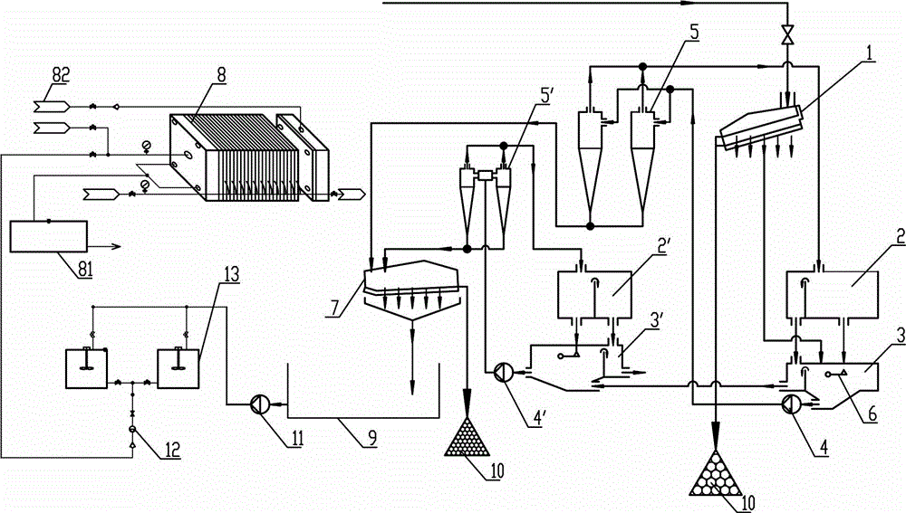
[0027] Such as figure 1 Among them, a mud treatment system, the bottom flow port of the pre-screen 1 is connected to the first slurry storage tank 3, and the screen of the pre-screen 1 is transported to the stockyard 10.

[0028] The bottom outlet of the first slurry storage tank 3 is connected to the inlet of the primary cyclone 5 through the first slurry pump 4, and the overflow port of the primary cyclone 5 is connected to the liquid inlet of the first overflow tank 2, The slurry outlet 205 of the first overflow box 2 is connected to the first slurry storage tank 3, and the bottom flow port of the primary cyclone 5 is connected to the bottom flow collection tank 9;

[0029] The overflow port of the first overflow tank 2 is connected to the second slurry storage tank 3', and the bottom outlet of the second slurry storage tank 3' is connected to the inlet of the secondary cyclone 5' through the second slurry pump 4', The underflow port of the secondary cyclone 5' is connecte...


PUM


Abstract

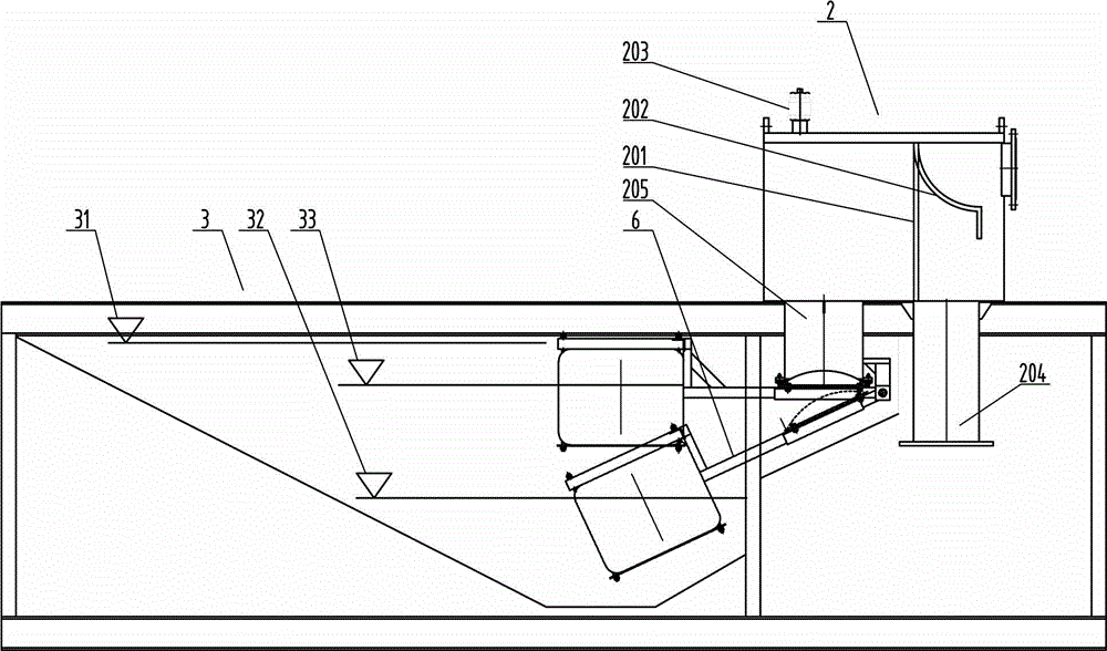
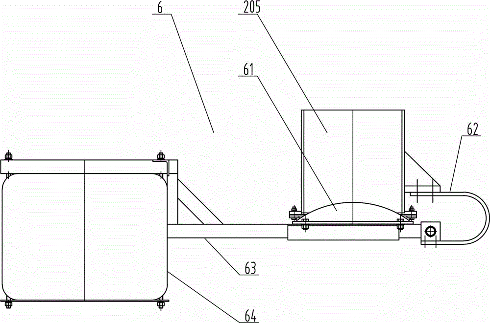
The invention relates to a sludge treatment system. An underflow opening of a pre-screen is connected with a first slurry storage tank; an underflow opening of the first slurry storage tank is connected with an inlet of a primary cyclone through a first slurry pump; an overflow port of the primary cyclone is connected with a liquid inlet port of a first overflow box; an underflow opening of the primary cyclone is connected with an underflow collecting tank; an overflow port of the first overflow box is connected with a second slurry storage tank; an underflow opening of the second slurry storage tank is connected with an inlet of a secondary cyclone through a second slurry pump; an underflow opening of the secondary cyclone is connected with the underflow collecting tank; an overflow port of the secondary cyclone is connected with a liquid inlet port of a second overflow box; a slurry discharge port of the second overflow box is connected with the second slurry storage tank; the underflow collecting tank is connected with a filter press or centrifuge; and a liquid level balance valve is arranged and used for plugging the slurry discharge port of the overflow box along with the liquid level height. The process route is optimized to enhance the sludge treatment efficiency. The slurry storage tanks capable of automatically implementing liquid level balance are matched to avoid idle suction of the slurry pump.

Description

technical field [0001] The invention relates to the field of mud treatment in the field of environmental protection, in particular to a mud treatment system. Background technique [0002] In the field of sludge or construction mud treatment, it is necessary to realize mud-water separation, river and lake dredging, urban pipe network sludge reduction treatment, tailings dry discharge, urban sewage treatment plant sludge desanding, etc. The requirements for the treated slurry When the discharge standard or recycling standard is met, the solid waste residue is landfilled, incinerated or recycled. [0003] At present, after the commonly used process mud is treated by a cyclone, the mud is dehydrated by a dewatering screen after being treated by a cyclone. After dehydration by the dewatering screen, the underflow continues to be separated by a cyclone, which increases the power consumption of the cyclone and the dewatering screen. [0004] In the previous mud treatment equipment...

Claims


Application Information

Patent Timeline
Patent Type & Authority Applications(China)
IPC IPC(8): C02F11/12
Inventor 张沛强涂晓琴金津邓金金
Owner 三川德青工程机械有限公司
Learn More