
Data protection in data storage system

Active Publication Date: 2005-03-03
SAMSUNG ELECTRONICS CO LTD +1
View PDF6 Cites 13 Cited by
  • Summary
  • Abstract
  • Description
  • Claims
  • Application Information

AI Technical Summary

Benefits of technology

[0015] The present invention may be practiced to particular advantage when the data storage syste

Problems solved by technology

However, when a printed circuit board (PCB) to which the firmware is loaded is switched with another PCB that does not lock the firmware, data in the hard disk drive is accessible to unauthorized users just as in a hard disk drive where the firmware is not locked.

Method used

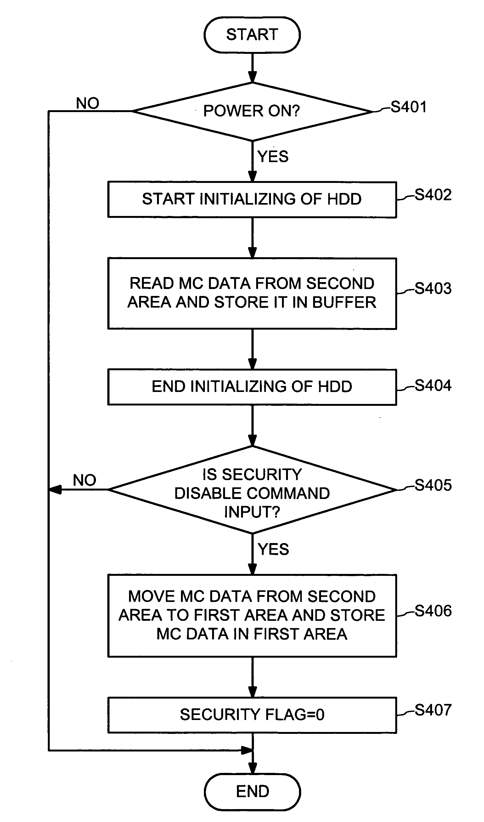
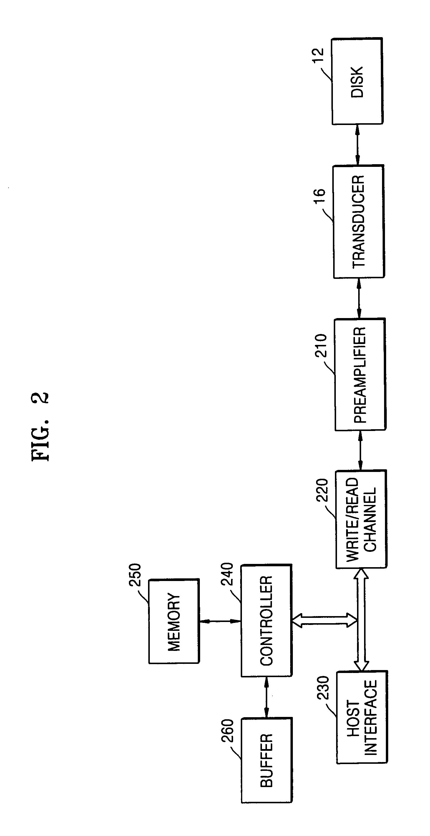

Image

  • Data protection in data storage system
  • Data protection in data storage system
  • Data protection in data storage system

Examples


Embodiment Construction

[0026] Hereinafter, embodiments of the present invention are described in detail with reference to the accompanying drawings. The present invention is described herein for a HDD (hard disk drive). However, the present invention may be practiced for protecting data in any other types of data storage systems.

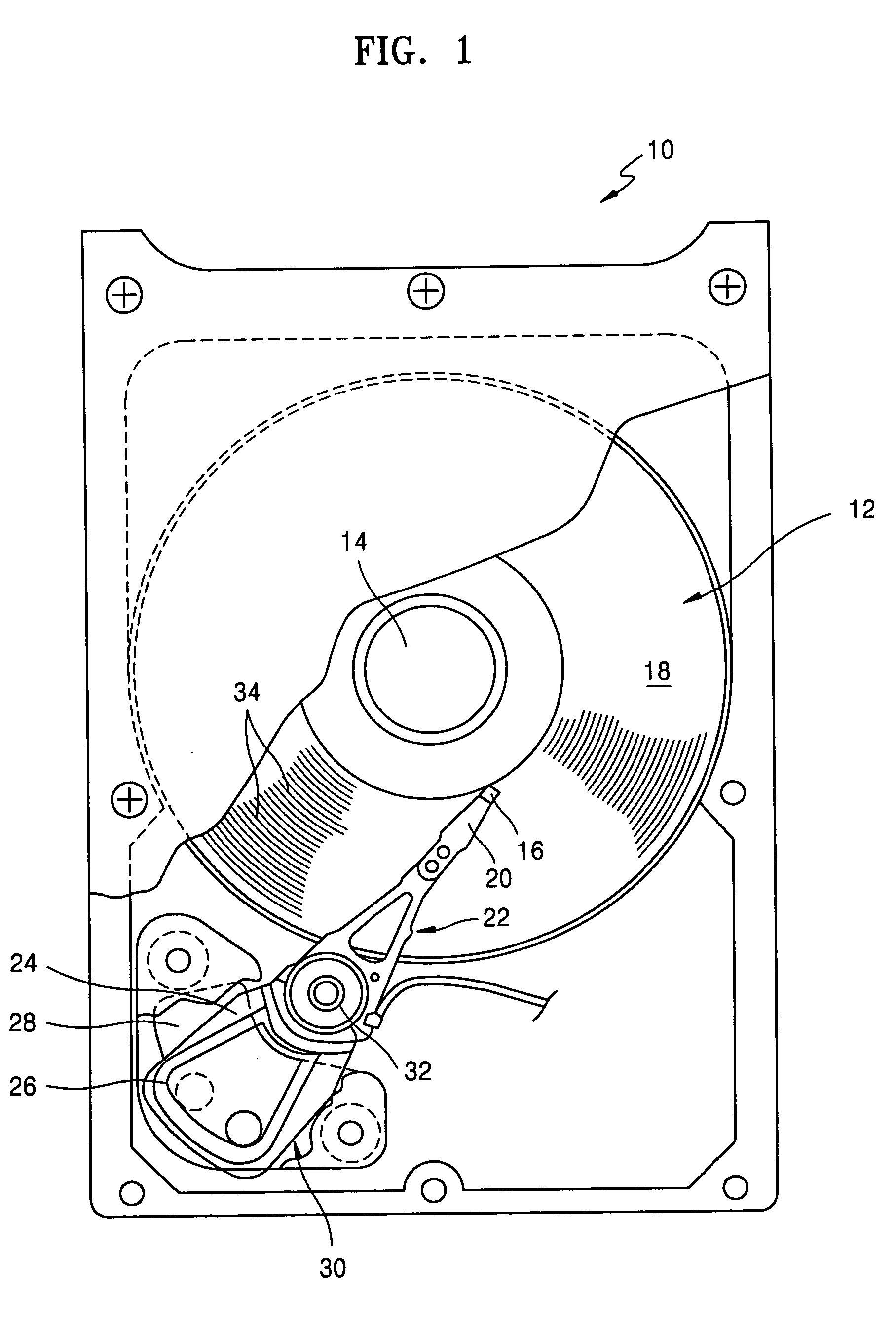
[0027]FIG. 1 is a plan view of a disk drive 10 according to an embodiment of the present invention. Referring to FIG. 1, the disk drive 10 includes at least one magnetic disk 12 which is rotated by a spindle motor 14. The disk drive 10 also includes a transducer 16 disposed over a disk surface 18.

[0028] The transducer 16 writes / reads information by magnetizing / sensing the magnetic field of the disk surface 18 as the transducer 16 flies over the disk surface 18. For simplicity and clarity of illustration, FIG. 1 illustrates the disk drive 10 having a single transducer 16. However, a transducer unit typically includes two types of transducers: a recording transducer that magnetize...


PUM


Abstract

For protecting data within a data storage system, such as a hard disk drive, security enable mode is entered. In that mode, initialization data is moved from a first area of a disk to a second area of the disk with a location of the second area being randomly generated. The initialization data is then erased from the first area. Also, a first cipher for firmware and a second cipher for a disk are both changed into a randomly generated value. Later, access to the initialization data from the second area is granted in the security enable mode if the first and second ciphers are the same.

Description

BACKGROUND OF THE INVENTION [0001] This application claims priority to Korean Patent Application No. 2003-0060206, filed on Aug. 29, 2003, in the Korean Intellectual Property Office, the disclosure of which is incorporated herein in its entirety by reference. [0002] 1. Field of the Invention [0003] The present invention relates generally to data storage systems such as hard disk drives, and more particularly, to data protection such that data stored within the data storage system is not available to an unauthorized user. [0004] 2. Description of the Related Art [0005] An example data storage system is a HDD (hard disk drive). Initial supply of power to a hard disk drive starts an initialization process. During the initialization process, a spindle motor and a head are moved over a predetermined area of a disk for reading maintenance cylinder (MC) data thereon. Such MC data is then stored within a buffer. [0006] The predetermined area of the disk where the MC data is stored is normal...

Claims


Application Information

Patent Timeline
IPC IPC(8): G06F21/24G06F3/06G06F12/14G06F21/00G06F21/02G11B20/10H04L1/00
CPCG06F21/80G11B20/10
Inventor CHO, SUNG-YOUNJEONG, SEUNG-YOULPARK, JONG-LAKSOHN, HAK-YEOL
Owner SAMSUNG ELECTRONICS CO LTD
Learn More