Torsional active vibration control system

a technology of vibration control system and torsional load, which is applied in the direction of shock absorbers, mechanical instruments, inertia effect dampers, etc., can solve the problems of generating noise, rarely uniform and often subjected to constant torsional load of propshafts

Inactive Publication Date: 2005-03-10
AMERICAN AXLE & MFG
View PDF37 Cites 4 Cited by
  • Summary
  • Abstract
  • Description
  • Claims
  • Application Information

AI Technical Summary

Benefits of technology

[0006] In one form, the present teachings provide a method for damping torsional vibrations in a rotating shaft. The method includes coupling an actuator to a shaft; rotating the shaft; determining an amount of torsional vibration in the shaft; and controlling the actuator in response to the amount of torsional vibration and a rotational position of the shaft to damp the torsional vibration in the shaft.

Problems solved by technology

As is well known in the art, the torsional loading of the propshaft is rarely uniform over an extended period of time even at relatively constant vehicle speeds and as such, the propshaft is typically subjected to a continually varying torsional load.
These variances in the torsional load carried by the propshaft tend to create torsional vibrations which may generate noise in the vehicle drivetrain or vehicle that is undesirable to passengers riding in the vehicle.
In especially severe instances, the vibration that is transmitted through the propshaft can generate fatigue in the propshaft and other drivetrain components to thereby shorten the life of the vehicle drivetrain.
One such drawback is that these devices are usually tuned to a specific frequency and consequently, will only damp vibrations within a relatively narrow frequency band.
Another drawback with conventional mechanical damping devices relates to their incorporation into an application, such as an automotive vehicle.
Generally speaking, these devices tend to have a relatively large mass, rendering their incorporation into a vehicle difficult due to their weight and overall size.
Another concern is that it is frequently not possible to mount these devices in the position at which they would be most effective, as the size of the device will often not permit it to be packaged into the vehicle at a particular location.

Method used


Image

  • Torsional active vibration control system
  • Torsional active vibration control system
  • Torsional active vibration control system

Examples


Embodiment Construction

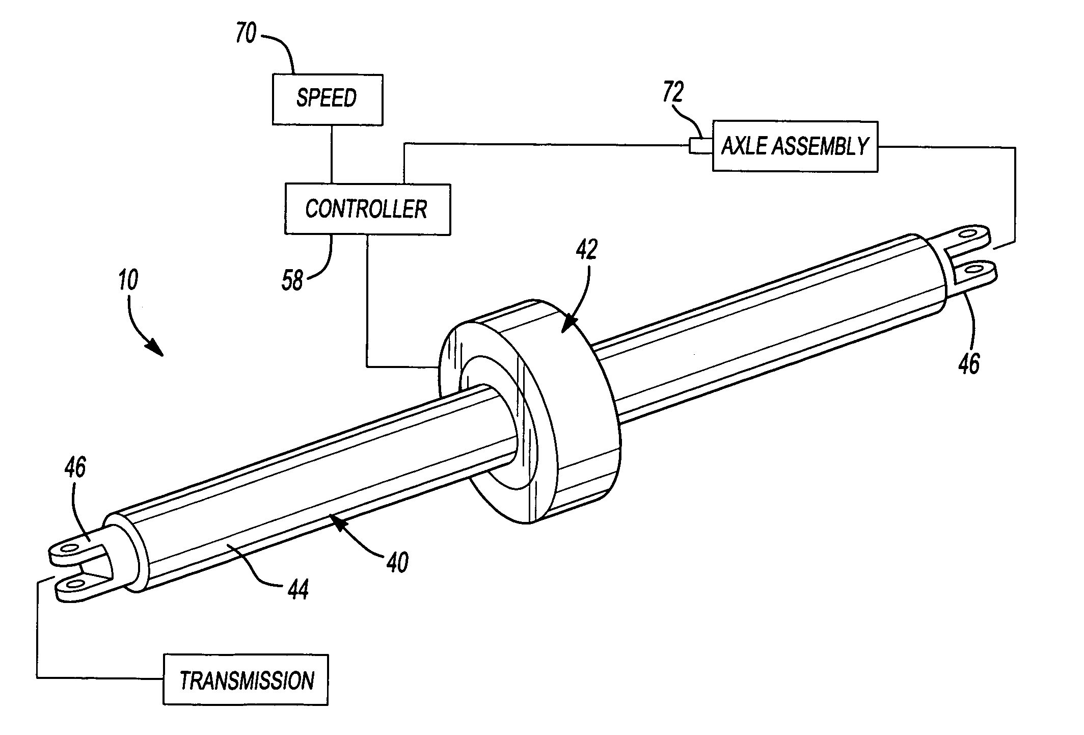
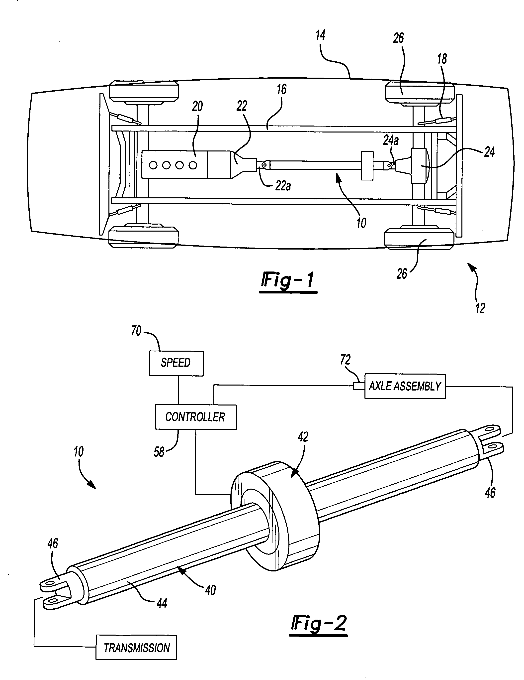
[0013] With reference to FIG. 1 of the drawings, a propshaft assembly constructed in accordance with the teachings of the present invention is generally indicated by reference numeral 10. The propshaft assembly 10 is illustrated in operative associate with an exemplary vehicle 12. The vehicle 12 conventionally includes a vehicle body 14, a chassis 16, a suspension system 18, a motor 20, a transmission 22 and an axle assembly 24. As the construction and operation of the vehicle body 14, chassis 16, suspension system 18, motor 20, transmission 22 and axle assembly 24 are well known to those skilled in the art, these components need not be discussed in significant detail.

[0014] Briefly, the suspension system 18 resiliently couples the axle assembly 24 to the vehicle chassis 16. The transmission 22, which receives a rotary output from the motor 20, includes a plurality of gear ratios (not specifically shown) that are employed to selectively change the speed ratio of a transmission outp...


PUM


Abstract

A method for damping torsional vibrations in a rotating shaft. The method includes coupling an actuator to a shaft; rotating the shaft; determining an amount of torsional vibration in the shaft; and controlling the actuator in response to the amount of torsional vibration and a rotational position of the shaft to damp the torsional vibration in the shaft.

Description

CROSS-REFERENCE TO RELATED APPLICATIONS [0001] This application is a divisional application of U.S. application Ser. No. 10 / 269,354 filed Oct. 11, 2002.FIELD OF THE INVENTION [0002] The present invention generally relates to devices for controlling noise, vibration and harshness (NVH) and more particularly to a method for actively reducing or canceling vibration in a rotating shaft. BACKGROUND OF THE INVENTION [0003] Propshafts are commonly employed for transmitting power from a rotational power source, such as the output shaft of a vehicle transmission, to a rotatably driven mechanism, such as a differential assembly. As is well known in the art, the torsional loading of the propshaft is rarely uniform over an extended period of time even at relatively constant vehicle speeds and as such, the propshaft is typically subjected to a continually varying torsional load. These variances in the torsional load carried by the propshaft tend to create torsional vibrations which may generate ...

Claims


Application Information

Patent Timeline
Patent Type & Authority Applications(United States)
IPC IPC(8): F16F15/00F16F15/121F16F15/126F16F15/14F16F15/18
CPCF16F15/005F16F15/1212F16F15/126Y10T464/50F16F15/18F16C3/023F16F15/1414F16C2326/06F16F15/10
Inventor SCHANKIN, DAVID PAULRANEK, MARK NORMANSAGADY, DANIEL VICTOR
Owner AMERICAN AXLE & MFG
Why Eureka
Try Eureka