Vibration control systems and methods for industrial lift trucks

a technology for industrial lift trucks and vibration control systems, applied in vessel construction, steering initiations, instruments, etc., can solve the problems of disconcerting operator motion, lift trucks, oscillating or vibrating about, etc., to reduce or eliminate the vibration of the truck, effectively cancel or damp the torsional vibration, and improve the effect of vibration control

Active Publication Date: 2014-08-07
RAYMOND LTD
View PDF2 Cites 8 Cited by
  • Summary
  • Abstract
  • Description
  • Claims
  • Application Information

AI Technical Summary

Benefits of technology

[0010]Embodiments of the present invention overcome the drawbacks of previous methods by providing systems and methods for improving the vibration control of a lift truck by providing additional stability control features to reduce or eliminate vibrating motion of the truck about the Z-axis. Embodiments of the present invention induce a counter moment to effectively cancel or damp the torsional vibrations, particularly in lift trucks having tall masts and in lift trucks that can provide right angle stacking, for example. The counter moment systems and methods can provide smoother ride characteristics and facilitate improved load handling by providing a more stable ride for the operator.

Problems solved by technology

One problem with lift trucks is that they can oscillate or vibrate about any of the X-axis, Y-axis and Z-axis (see FIG. 1).
While such torsional motion will not tip the truck, the motion can be disconcerting to the operator.
These unwanted vibrations can reduce the efficiency of the operator and the overall productivity of lift truck operations.
Another problem seen by lift trucks traveling throughout a facility is that they can encounter debris on the floor and uneven floor surfaces.
These can take the form of expansion joints, cracks in the floor surface or man-made objects such as ramps going between buildings or into tractor trailers.
Tire irregularities and / or the floor can also cause periodic vibrations that can be transmitted throughout the truck's frame.
The vibrations caused by the floor condition can diminish the effectiveness and / or accuracy of sensory equipment on the truck and may necessitate that the truck be operated at slower speeds to reduce the effects of the floor conditions.
Slower operating speeds can equate to an undesirable reduction in overall equipment productivity.
Most previously used methods to dissipate vibrations have only attempted to address longitudinal vibrations, and do not address torsional vibrations.
This adds cost and weight, and further areas for mechanical issues.

Method used


Image

  • Vibration control systems and methods for industrial lift trucks
  • Vibration control systems and methods for industrial lift trucks
  • Vibration control systems and methods for industrial lift trucks

Examples


Embodiment Construction

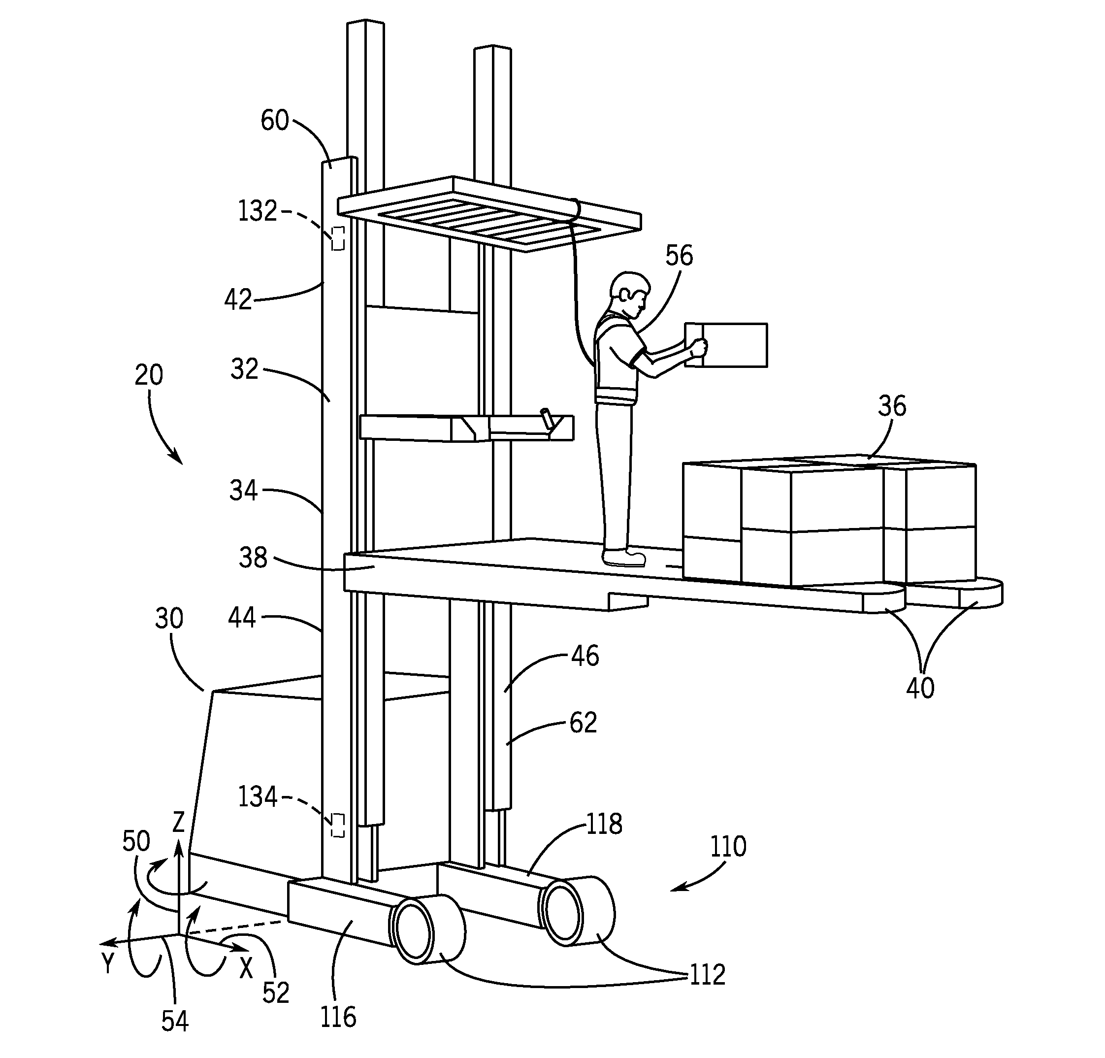
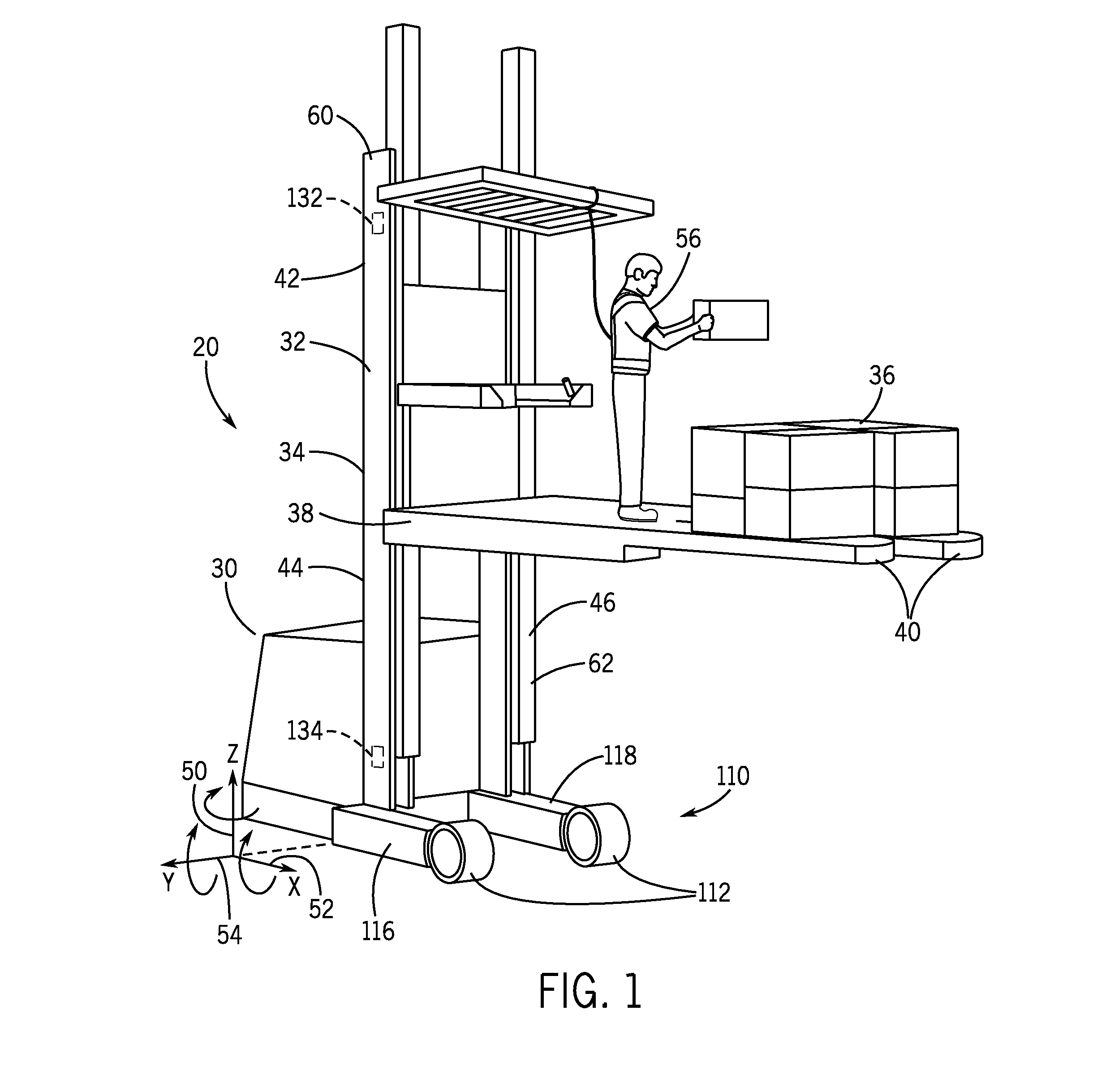
[0022]The various aspects of the invention will be described in connection with improved vibration control of industrial lift trucks. That is because the features and advantages that arise due to embodiments of the invention are well suited to this purpose. Still, it should be appreciated that the various aspects of the invention can be applied to achieve other objectives as well.

[0023]While the description of embodiments of the invention and the accompanying drawings generally refer to a man-up orderpicker style lift truck, it is to be appreciated that embodiments of the invention can be applied to control unwanted torsional vibrations in any lift truck configuration. Other vehicles that can benefit from embodiments of the invention include a reach truck, a high-lift truck, a counterbalanced truck, and a swing-reach truck, as non-limiting examples.

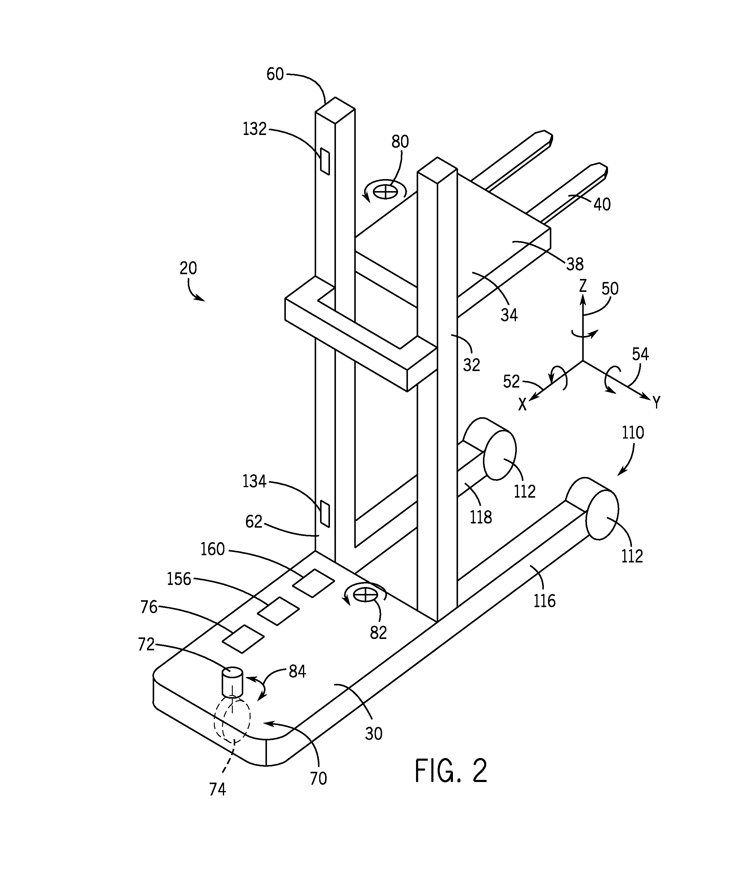
[0024]Referring to FIG. 1, a lift truck 20 can comprise a tractor unit 30 coupled to a mast 32. The mast 32 can be vertically extendable...


PUM


Abstract

A lift truck includes systems and methods for improved vibration control. A corrective yaw input mechanism reduces or eliminates torsional vibration motion of the lift truck about the Z-axis. Some embodiments may include, alone or in combination, drive wheel control and load wheel control.

Description

CROSS-REFERENCE TO RELATED APPLICATIONS[0001]Not applicable.STATEMENT CONCERNING FEDERALLY SPONSORED RESEARCH OR DEVELOPMENT[0002]Not applicable.FIELD OF THE INVENTION[0003]The present invention relates to the field of industrial lift trucks, and more specifically to systems and methods for improved vibration control for lift trucks.BACKGROUND OF THE INVENTION[0004]Lift trucks are designed in a variety of configurations to perform a variety of tasks. One problem with lift trucks is that they can oscillate or vibrate about any of the X-axis, Y-axis and Z-axis (see FIG. 1). For example, when an operator stops the truck abruptly or abruptly changes direction, or both, torsional vibrating motion about the Z-axis (also referred to as yaw) can be felt by the lift truck operator. The vibrations can be more noticeable when the lift truck's mast is vertically extended. While such torsional motion will not tip the truck, the motion can be disconcerting to the operator. Normally an operator wi...

Claims


Application Information

Patent Timeline
Patent Type & Authority Applications(United States)
IPC IPC(8): B66F17/00
CPCB66F17/003
Inventor GONCALVES, FERNANDO D.KIRK, JOHN BRYANTMEDWIN, STEVEN J.
Owner RAYMOND LTD
Why Eureka
Try Eureka