Frame interpolation method and apparatus, and image display system

a frame interpolation and image technology, applied in the field of frame interpolation methods and apparatus, and image display systems, can solve problems such as block distortion on the boundary between images

Inactive Publication Date: 2005-03-10
TOSHIBA VISUAL SOLUTIONS CORPORATION
View PDF2 Cites 55 Cited by
  • Summary
  • Abstract
  • Description
  • Claims
  • Application Information

AI Technical Summary

Benefits of technology

[0013] An aspect of the invention provides an image interpolation method of interposing an interpolation image between a first reference image and a second reference image adjacent to the first reference image in terms of time, the method comprising: searching a motion vector from different pairs of blocks on the first reference image and the second reference image symmetrically; extracting a first image block and a second image block from the first reference image and the second reference image, respectively, the first image block and the second image block being located by the motion vector; determining a region determination threshold using an absolute difference between paired opposite pixels of the first image block and the second image block; extracting from each of the first image block and the second image block a first pixel region that the absolute difference is smaller than the region determination threshold; and obtaining a pixel value of a second pixel region of the to-be-interpolated block from a pixel value of the first pixel region of each of the first image block and the second image block, the second pixel region corresponding to the first pixel region.

Problems solved by technology

In a hold model picture display apparatus which continues to display a previous frame till an image is newly written in, such as a liquid crystal display and an electroluminescence display, there are problems such as a blurring occurring when eyes of a viewer follow movement of a moving object in a video display, and an unnatural movement due to displaying a video with a few frames.
For this reason, there is a problem that a block distortion occurs on a boundary between the image blocks on the interpolation frame in the case that there are a plurality of movements in the image block.

Method used


Image

  • Frame interpolation method and apparatus, and image display system
  • Frame interpolation method and apparatus, and image display system
  • Frame interpolation method and apparatus, and image display system

Examples


first embodiment

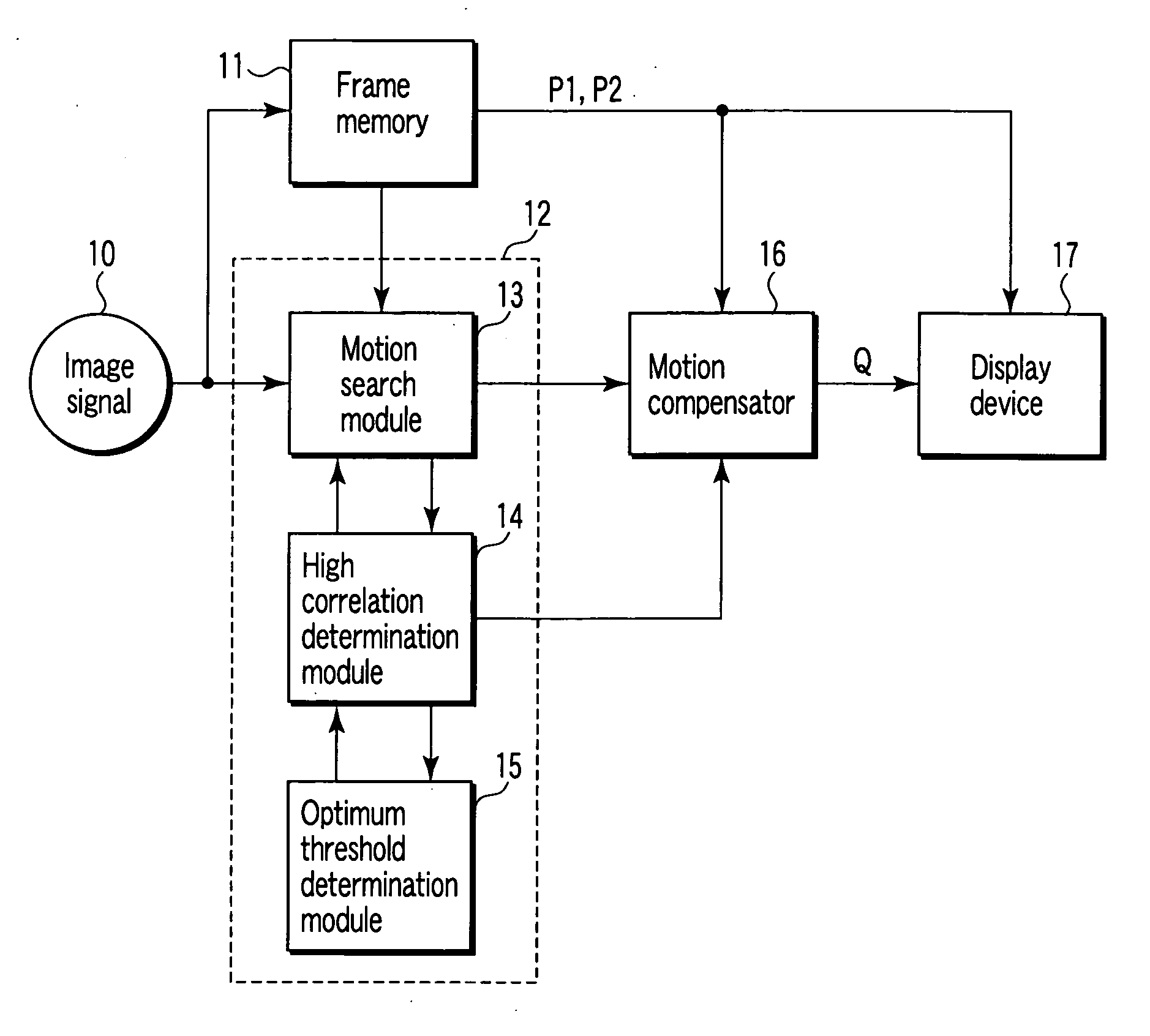
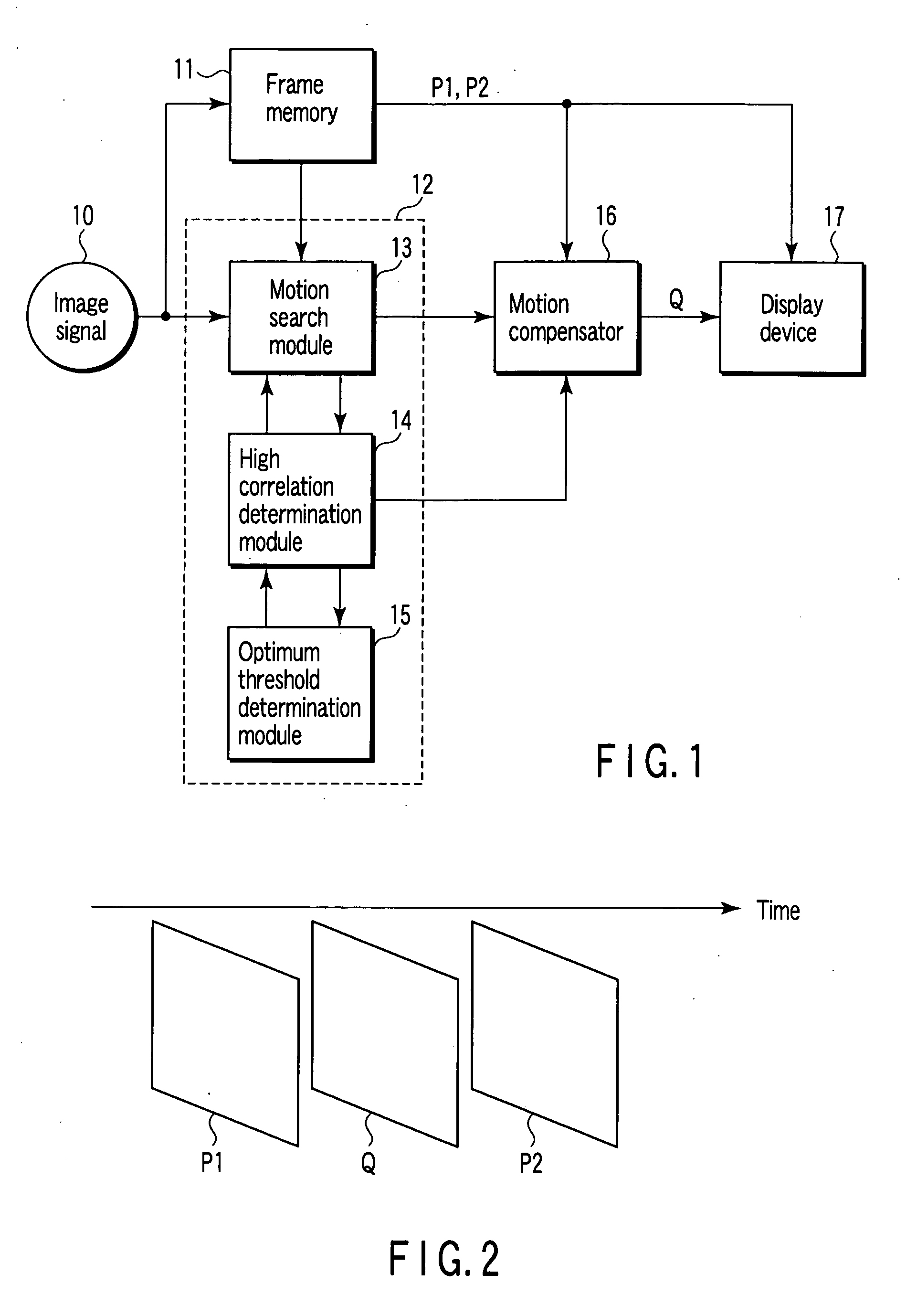
[0044]FIG. 1 shows a configuration of a video display system related to the present invention. There is described an example to convert an input picture signal (video signal) 10 which is a non-interlace signal of 60 Hz (progressive signal) into a non-interlace signal of 120 Hz.

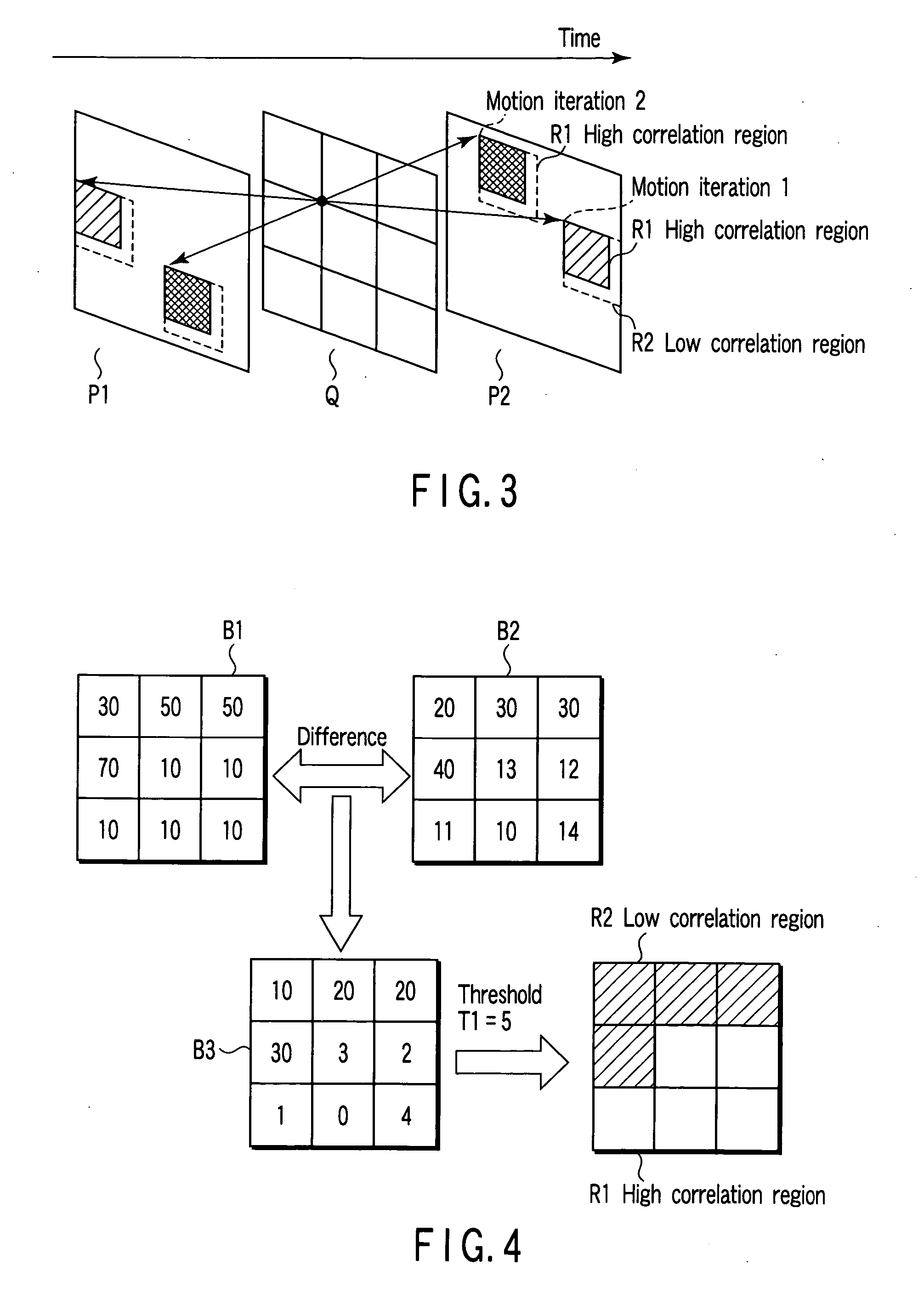
[0045] Frame interpolation in the present embodiment is realized by interpolating an interpolation frame Q (at a middle position in terms of time between reference frames P1 and P2 (images)) between the two reference frames P1 and P2 adjacent in terms of time with respect to the non-interlace input signal of 60 Hz as shown in FIG. 2.

[0046] In FIG. 1, the video signal 10 is input to a frame memory 11 and a motion estimation unit 12. The motion estimation unit 12 comprises a movement motion search module 13, a high correlation region determination division module 14 and an optimum threshold determination module 15. The movement search module 13 searches for a motion vector between the reference frames P1 and P2...

second embodiment

[0102] (Second Embodiment)

[0103] In the image display system concerning the second embodiment of the present invention as shown in FIG. 24, a motion vector candidate search unit 18 is added to the image display system shown in FIG. 1. When the motion vector candidate search unit 18 searches for a candidate of a motion vector used for setting the optimum region determination threshold value in the optimum threshold determination unit 15.

[0104] In searching for the motion vector, the sum of high correlation pixels (Muximum matching Pel Count, referred as to MPC) as shown hereinafter can be used as an evaluation function. MPC=∑x=1N⁢ ⁢∑y=1M⁢ ⁢{1(fp1⁡(x,y)-fp2⁡(x,y)<T)0(otherwise)(6)

[0105] fpi(x, y) indicates a pixel value in the point (x, y) of the reference frame P1, f p2(x, y) a pixel value in the point (x, y) of the reference frame P2, T a threshold (for example, 3, etc.), and (N,M) a size of image. MPC is one focused in a shape such as an object. It is necessary for the thresho...


PUM


Abstract

An image interpolation method comprises searching a motion vector from different pairs of blocks on a first and a second reference image symmetrically, extracting a first and a second image block from the first and the second reference image, respectively, the first and the second image block being located by the motion vector, determining a region determination threshold using an absolute difference between paired opposite pixels of the first and the second image block, extracting from each of the first and the second image block a first pixel region that the absolute difference is smaller than the region determination threshold, and obtaining a pixel value of a second pixel region of the to-be-interpolated block from a pixel value of the first pixel region of each of the first and the second image block, the second pixel region corresponding to the first pixel region.

Description

CROSS-REFERENCE TO RELATED APPLICATIONS [0001] This application is based upon and claims the benefit of priority from prior Japanese Patent Application No. 2003-155463, filed May 30, 2003, the entire contents of which are incorporated herein by reference. BACKGROUND OF THE INVENTION [0002] 1. Field of the Invention [0003] The present invention relates to a frame interpolation method and apparatus of interposing at least one interpolation frame between adjacent frames for the purpose of decreasing a display frame interval in playing back a video image, and an image display system using the same. [0004] 2. Description of the Related Art [0005] In a hold model picture display apparatus which continues to display a previous frame till an image is newly written in, such as a liquid crystal display and an electroluminescence display, there are problems such as a blurring occurring when eyes of a viewer follow movement of a moving object in a video display, and an unnatural movement due to...

Claims


Application Information

Patent Timeline
Patent Type & Authority Applications(United States)
IPC IPC(8): G06K9/36G06K9/46H04N5/14H04N7/01H04N19/50H04N19/51H04N19/587H04N19/59H04N19/86
CPCH04N7/014H04N5/145
Inventor MISHIMA, NAOITO, GO
Owner TOSHIBA VISUAL SOLUTIONS CORPORATION
Why Eureka
Try Eureka