
Mop device having changeable abrasive strip

a technology of abrasive strip and a mop device, which is applied in the direction of carpet cleaners, cleaning machines, cleaning equipment, etc., can solve the problems of not being able to effectively mop or clean the ground or the surfaces that are required to be cleaned, and achieve the effect of effectively engaging with and effectively mopping the ground or the surfaces to be cleaned

Inactive Publication Date: 2005-03-17
OIMO INDAL
View PDF13 Cites 16 Cited by
  • Summary
  • Abstract
  • Description
  • Claims
  • Application Information

AI Technical Summary

Benefits of technology

[0011] The other objective of the present invention is to provide a mop device including an abrasive surface member that may be used to effectively mop the ground or the surfaces to be cleaned.
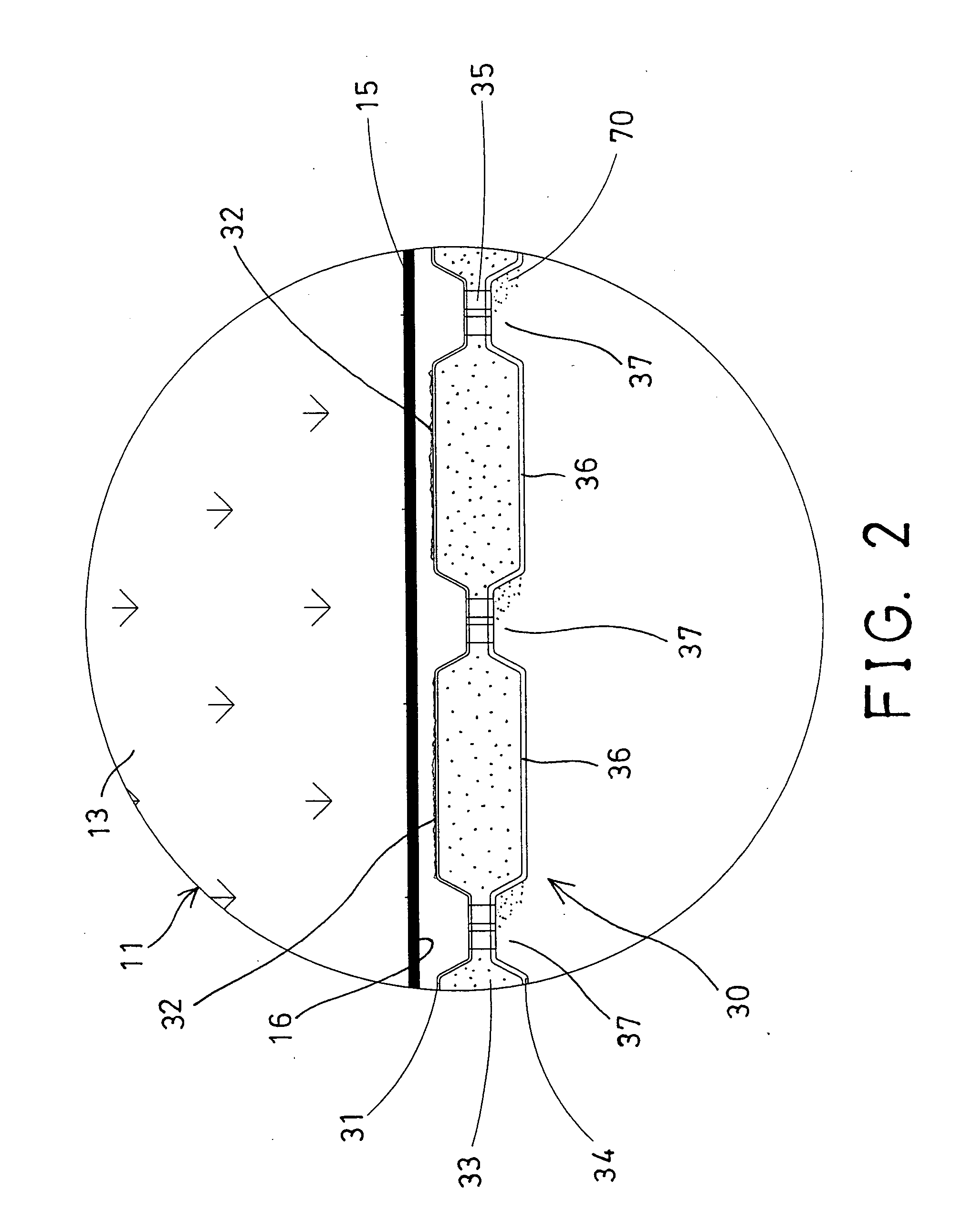
[0012] In accordance with one aspect of the invention, there is provided a mop device comprising a handle including a support element attached to bottom thereof, an abrasive surface member, and means for detachably attaching the abrasive surface member to the support element. The abrasive surface member includes a resilient element and a lower cover member secured together, to form at least one swelling and at least one depression in the abrasive surface member, and to effectively engage with ground or surfaces to be cleaned.
[0013] The lower cover member includes at least one side flange extended beyond the resilient element and foldable to engage with the support element. The side flange of the lower cover member includes at least one notch formed therein to define at least one flap therein, and to facilitate folding and engaging of the side flange of the lower cover member onto the support element.

Problems solved by technology

However, the spongy member is also solidly attached to the support element, and may not be detached or disengaged from the support element, and thus may not be changed with the new ones when the previous spongy member has been damaged or worn out.
In addition, the abrasive surface strips normally include a planar structure made of woven or non-woven cloth materials, which may not be used to effectively mop or clean the ground or the surfaces that are required to be cleaned.

Method used


Image

  • Mop device having changeable abrasive strip
  • Mop device having changeable abrasive strip
  • Mop device having changeable abrasive strip

Examples


Embodiment Construction

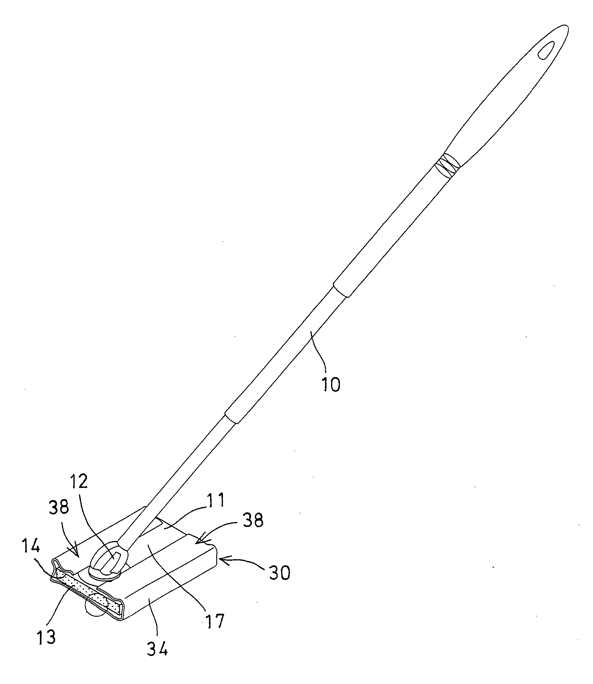
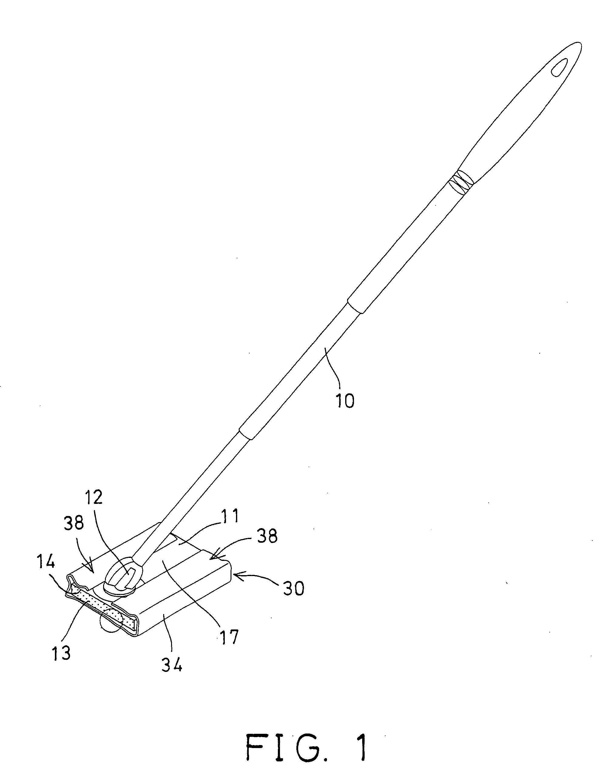
[0023] Referring to the drawings, and initially to FIG. 1, a mop device in accordance with the present invention comprises a handle 10, a support element 11 attached to the bottom of the handle 10 with such as a typical pivot joint or hinge 12, to allow the support element 11 to be pivoted or rotated relative to the handle 10.

[0024] A resilient or sponge member 13 may further be provided and attached to the bottom portion 14 of the support element 11, for resiliently or flexibly contacting with the ground or the other surfaces to be cleaned. A coupling device 15, such as a hook-and-loop coupling device 15 may further be provided and attached to the bottom portion 16 of the resilient or sponge member 13.

[0025] The mop device in accordance with the present invention further comprises an abrasive surface member 30 to be changeably or detachably and directly attached to the bottom portion 14 of the support element 11, or attached to the bottom portion 16 of the resilient or sponge mem...


PUM

PropertyMeasurementUnit
Abrasiveaaaaaaaaaa
Resilienceaaaaaaaaaa
Swelling volumeaaaaaaaaaa

Abstract

A mop device includes a support element attached to bottom of a handle, and an abrasive surface member detachably attached to the support element. The abrasive surface member includes a resilient element and a lower cover member secured together, to form one or more swellings and one or more depressions in the abrasive surface member, and to effectively engage with and mop the ground or surfaces to be cleaned. The abrasive surface member includes an upper cover sheet secured onto the resilient element with one or more coupling elements, and one or more coupling devices attached to the cover sheet for securing to the support element.

Description

BACKGROUND OF THE INVENTION [0001] 1. Field of the Invention [0002] The present invention relates to a mop device, and more particularly to a mop device having an abrasive surface member changeably or detachably attached to the mop device. [0003] 2. Description of the Prior Art [0004] Various kinds of typical mop devices have been developed and provided for mopping the ground or the surfaces to be cleaned, and normally comprise a spongy member solidly attached to a support element, for cleaning purposes. [0005] For example, U.S. Pat. No. 5,483,720 to Decoopman et al. discloses one of the typical mop devices which also comprises a spongy member solidly attached to a support element, for cleaning purposes. The spongy member may not be detached or disengaged from the support element, and thus may not be changed with the new ones when the previous spongy member has been damaged or worn out. [0006] U.S. Pat. No. 5,488,750 to Vosbikian et al. discloses another typical mop device comprisin...

Claims


Application Information

Patent Timeline
IPC IPC(8): A47L13/20A47L13/256
CPCA47L13/256A47L13/20
Inventor LIN, PAI YUNG
Owner OIMO INDAL
Learn More