Valve train for internal combustion engine

a technology for internal combustion engines and valve trains, which is applied in the direction of valve drives, machines/engines, mechanical equipment, etc., can solve the problems of increased torque required for turning the camshaft, insufficient low friction coefficient of dlc material, etc., to achieve excellent low-friction characteristics, improve vehicle fuel efficiency, and reduce the effect of dlc material scalding

Inactive Publication Date: 2005-03-17
NISSAN MOTOR CO LTD
View PDF99 Cites 44 Cited by
  • Summary
  • Abstract
  • Description
  • Claims
  • Application Information

AI Technical Summary

Benefits of technology

[0012] It is therefore an object of the present invention to provide a valve train that can attain excellent low-friction characteristics, high wear resistance, anti-seizing characteristic and durability by the combined use of a diamond-like carbon material and a lubricating oil, so that the valve train shows more improvements in vehicle fuel efficiency than that of the earlier technology.
[0013] The inventors of the present invention have found that a specified hard carbon film attained excellent low-friction characteristics, wear resistance, anti-seizing and durability under a condition that the hard carbon film is lubricated by a lubricating oil, specifically by a lubricating oil including an ashless friction modifier, attains, through intensive researches.

Problems solved by technology

However, it has been cleared that the DLC material does not provide such a low friction coefficient in the sliding members in the presence of lubricating oil and that the friction coefficient of the DLC material cannot be lowered to a sufficient degree even when used in combination with a lubricating oil containing organomolybdenum compound.
A valve train, particularly a camshaft and its surroundings, has had the problems that (1) a required torque for turning a camshaft is increased by an increase of a sliding resistance between cam lobes and valve lifters increases a required torque for turning a camshaft, and (2) the required torque for turning the camshaft also increased by an increase of sliding resistance between journal bearings of a cylinder head and camshaft journals.
Further, the valve train, particularly engine valves and their surroundings have had the problems that (1) it is difficult to further decease a clearance between a valve stem and a valve guide, (2) sticking or oil loss via valve guides will cause, if the lubrication of each valve stem is not sufficiently executed, (3) the reduction of a friction between a valve stem and a valve guide has almost reached a limit, and (4) a hammering of a valve against a valve seat of a cylinder head wears a valve face.

Method used


Image

  • Valve train for internal combustion engine
  • Valve train for internal combustion engine
  • Valve train for internal combustion engine

Examples


Embodiment Construction

[0018] The present invention will be described below in detail. In the following description, all percentages (%) are by mass unless otherwise specified.

[0019] Referring to the drawings, there is discussed a valve train including a camshaft in accordance with the present invention.

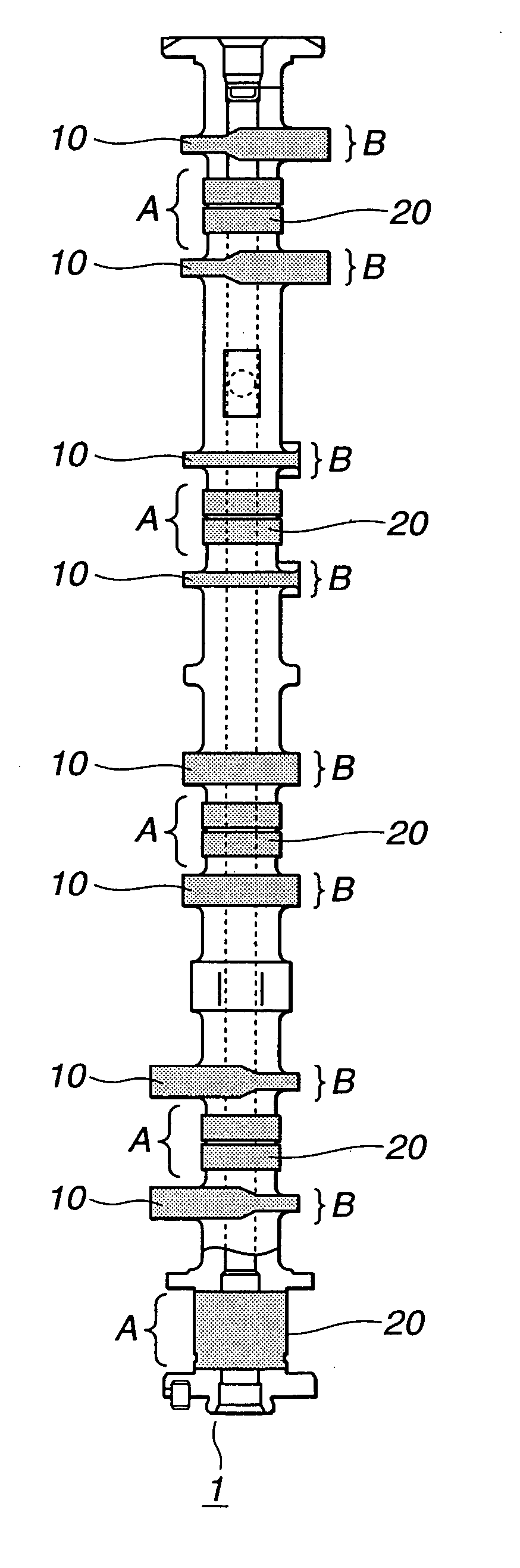
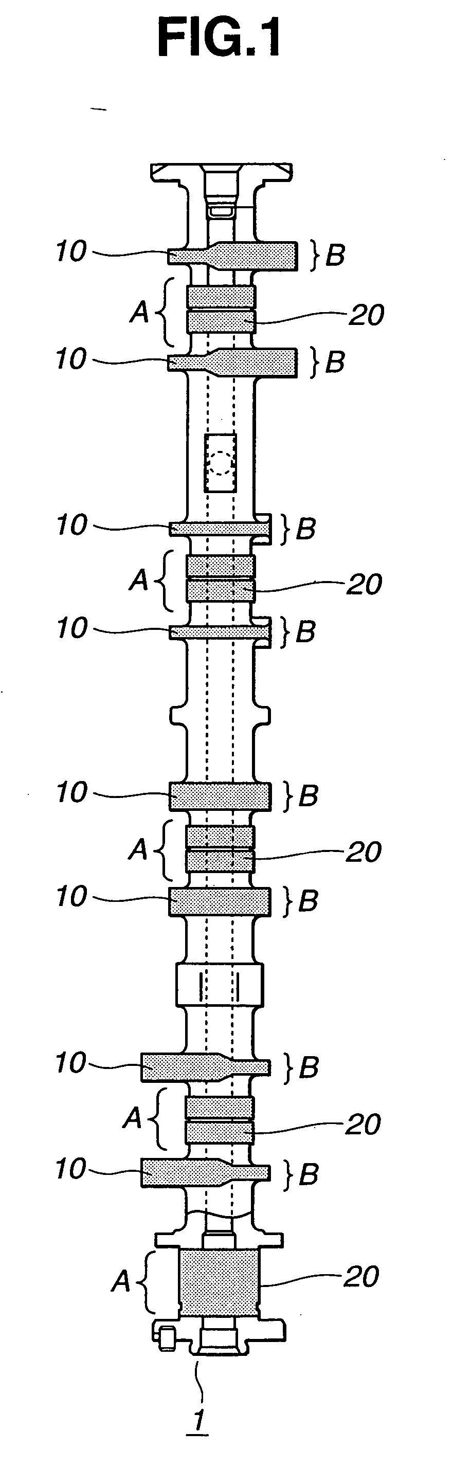
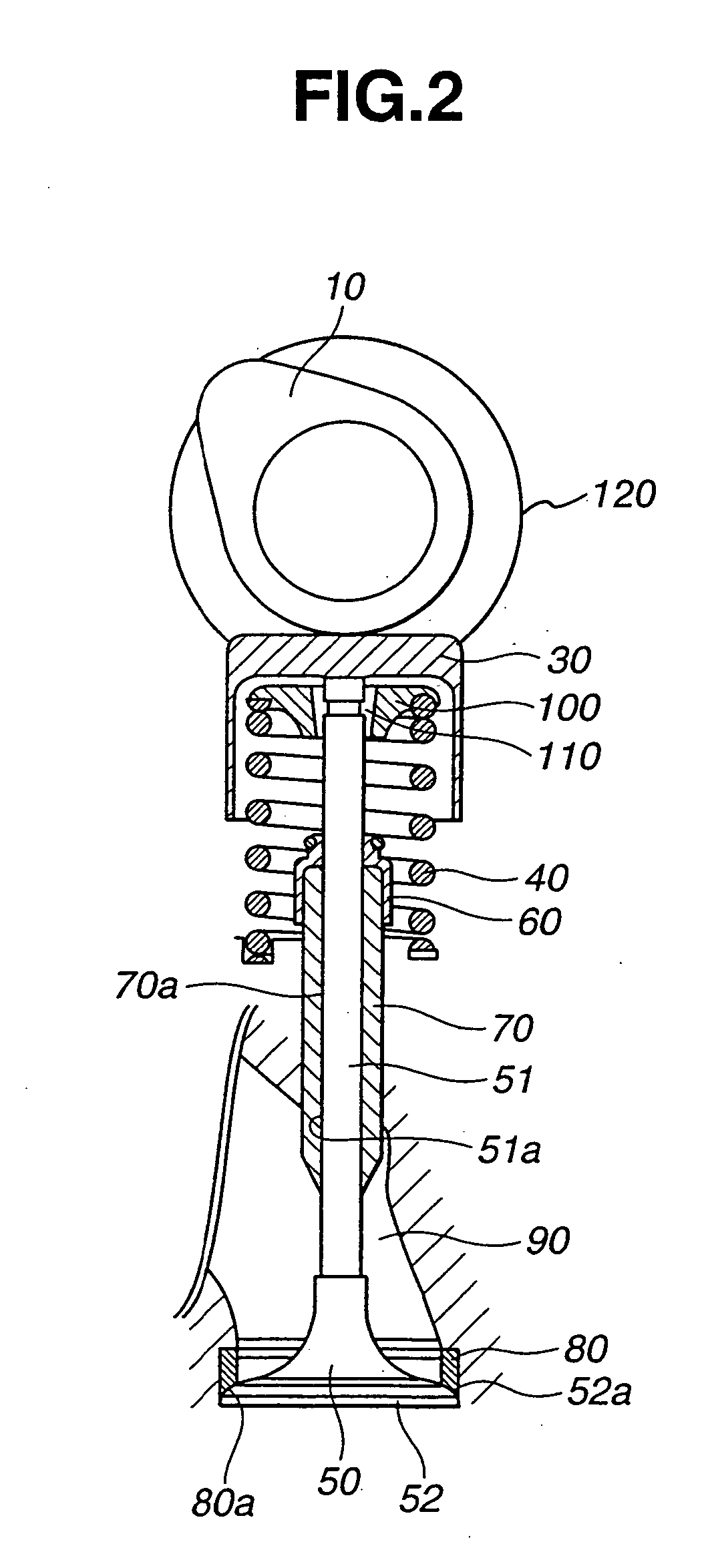
[0020] As shown in FIGS. 1 and 2, a camshaft 1 made of an iron-based material comprises cam lobes 19 and camshaft journals 20. Camshaft 1 turns by receiving a driving torque of an internal combustion engine (not shown) through a crankshaft (not shown) and a chain (not shown). Each cam lobes 10 pushes down each valve lifter 30 according to the revolution of camshaft 1 to execute opening and closing operation of each valve 50.

[0021] Camshaft 1 turns under a supported condition that camshaft journals 20 of camshaft 1 are supported by cylinder head brackets 120, respectively. Lubricating oil is supplied to a small clearance formed between each camshaft journal 20 and each cylinder head bracket 120 so as to ...


PUM

PropertyMeasurementUnit
surface roughnessaaaaaaaaaa
surface roughness Raaaaaaaaaaa
kinematic viscosityaaaaaaaaaa

Abstract

A valve train for an internal combustion engine is comprised of a lubricating oil, and a camshaft which is made of an iron-based material and comprises a cam lobe and a camshaft journal. The camshaft slidingly moves on a counterpart thereof through the lubricating oil. A hard carbon film is formed on at least one of a sliding portion of the camshaft and the counterpart made of an iron-based material. A hydrogen amount of the hard carbon film is 10 atomic percent or less.

Description

CROSS-REFERENCE TO RELATED APPLICATIONS [0001] This application has the following related applications: U.S. patent application Ser. Nos. 09 / 545,181 based on Japanese Patent Application Hei-11-102205 filed on Apr. 9, 1999; 10 / 468,713 which is the designated state (United States) application number of PCT Application JP02 / 10057 based on Japanese Patent Application 2001-117680 filed on Apr. 17, 2001; 10 / 355,099 based on Japanese Patent Application 2002-45576 filed on Feb. 22, 2002; 10 / 682,559 based on Japanese Patent Application No. 2002-302205 filed on Oct. 16, 2002; and 10 10 / 692,853 based on Japanese Patent Application 2002-322322 filed on Oct. 16, 2002.BACKGROUND OF THE INVENTION [0002] The present invention relates a valve train for an internal combustion engine, and more particularly to a valve train in which sliding portions of a camshaft and valves and / or counterparts thereof are coated with a hard carbon film (coating) such as a diamond-like carbon (DLC) film performing an ex...

Claims


Application Information

Patent Timeline
Patent Type & Authority Applications(United States)
IPC IPC(8): C10M101/02F01L1/04C10M129/70C10M133/06C10M133/56C10M137/10C10M139/00C10M169/06C10N10/04C10N30/06C10N40/25C10N60/14F01L1/047F01L1/14F01L1/18
CPCF01L2101/00F01L1/047F01L2301/00
Inventor NOMURA, SHINMIURA, TAKAHIROKANO, MAKOTOMABUCHI, YUTAKAHAMADA, TAKAHIROMURAKAMI, MIKI
Owner NISSAN MOTOR CO LTD
Why Eureka
Try Eureka