Endoscope magnetic rocker switch

a rocker switch and endoscope technology, applied in the field of switches, can solve the problems of reducing or eliminating the tactile feedback, unable to completely predict the movement of the magnet b>26/b>, and unable to emit audible sounds

Inactive Publication Date: 2005-03-17
LINVATEC
View PDF5 Cites 119 Cited by
  • Summary
  • Abstract
  • Description
  • Claims
  • Application Information

AI Technical Summary

Benefits of technology

[0007] A rocker switch on an endoscopic camera allows multiple functions from a single Hall effect sensor. The switch features a neutral position between a rocked forward and a rocked back position. When the front of the switch is depressed a dome spring under the front is flattened and the magnet located in the rear is moved away from the sensor. Releasing the switch returns it to the neutral position. Depressing the rear of the switch brings the magnet closer to the Hall effect sensor while depressing another dome spring under the rear of the switch. Again, releasing the switch returns it to the neutral position.

Problems solved by technology

In the switch of FIG. 1 the switch is limited to enabling a single function.
The use of a large mass of rubber for the button housing 32 dampens any audible sound made by the switch, when actuated, and severely reduces or eliminates the tactile feedback from the dome spring 22.
Another disadvantage is that the magnet 26 does not have completely predictable movements in response to pressure on the button housing 32.
Accordingly, its function is not always assured.
Additionally, the switch shown in FIG. 1 is relatively expensive to make.

Method used


Image

  • Endoscope magnetic rocker switch
  • Endoscope magnetic rocker switch
  • Endoscope magnetic rocker switch

Examples


Embodiment Construction

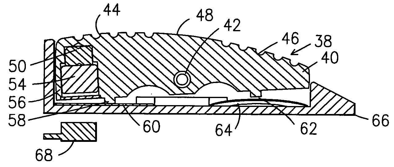
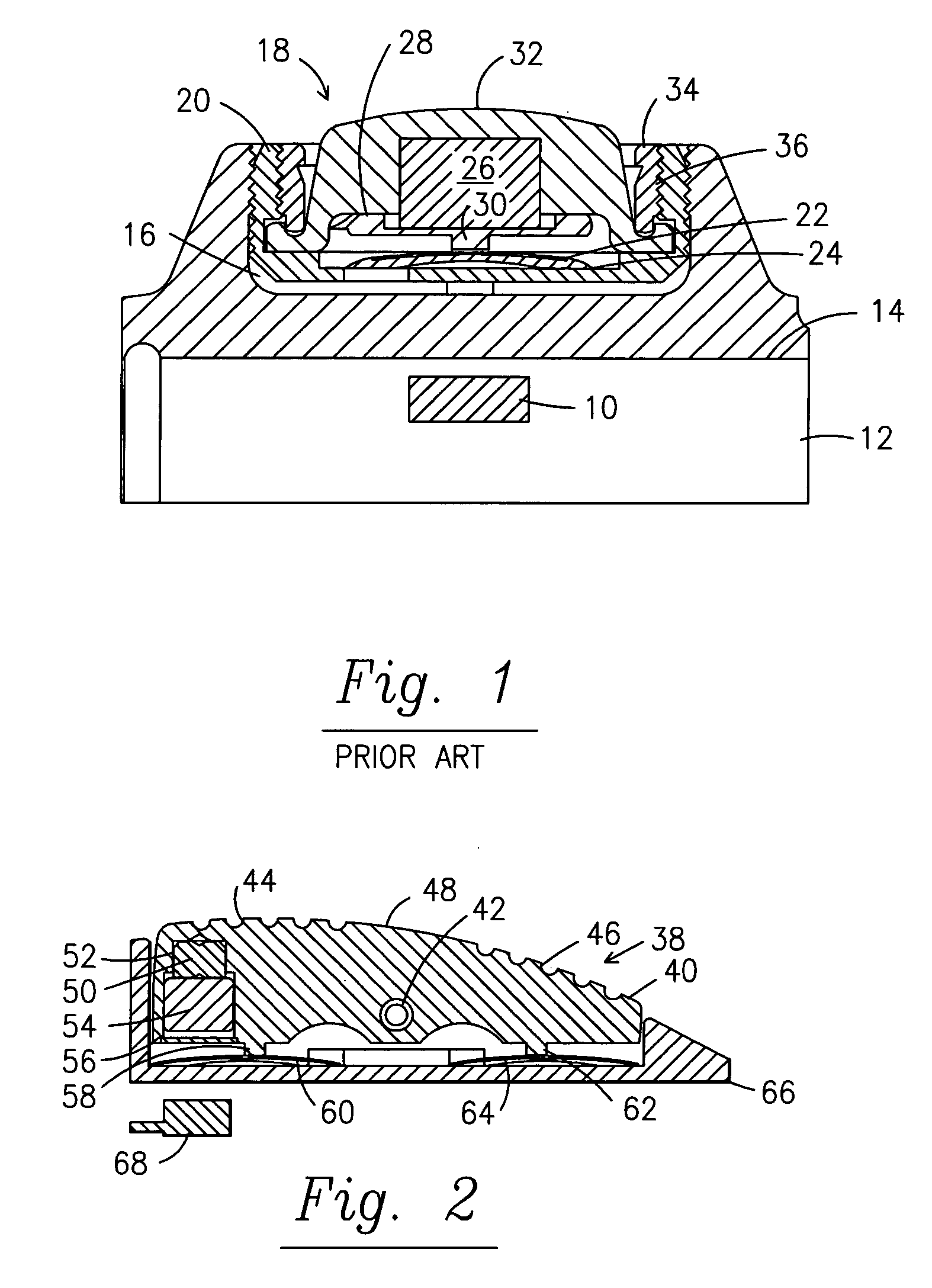
[0013]FIG. 2 illustrates the switch 38 in the neutral position. Switch 38 has a rocker 40 pivoted at 42 with rear undulations44 and front undulations 46 on top surface 48. A magnetic pin 50 is secured in a counter-bore 52. The magnet 54 is disposed in cavity 56 and is secured to the magnetic pin 50. Tab 58 extends down from rocker 40 toward dome spring 60. Tab 62 extends from rocker 40 toward dome spring 64 near the front of switch 38. In the neutral position of FIG. 2, both dome springs 60 and 64 are slightly, equally compressed. The switch 38 is disposed in an outer housing 66 that slides over the camera body (not shown except for the Hall sensor 68 that is preferably embedded in the camera body or the housing).

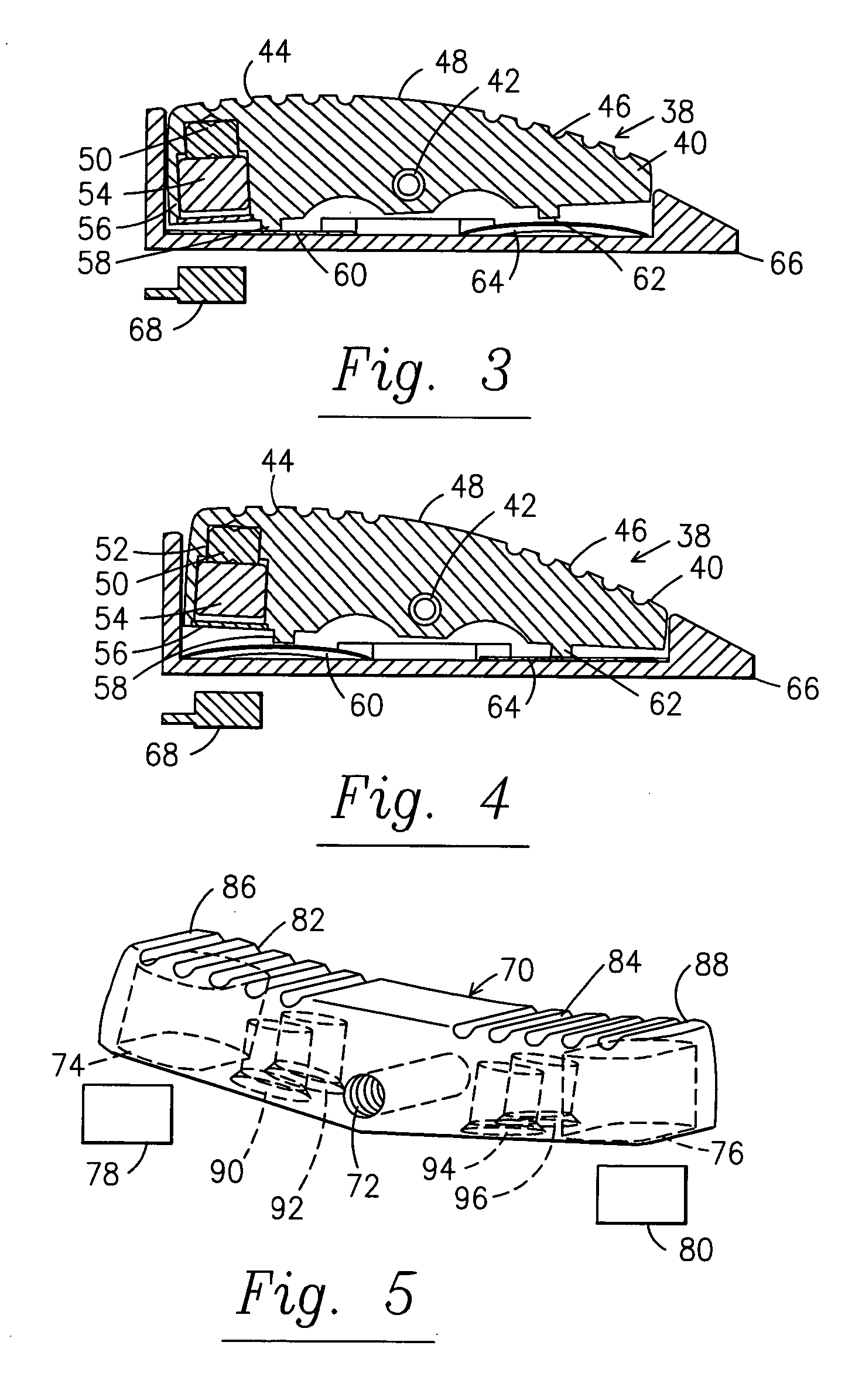
[0014] In operation, the surgeon depresses the rear of the switch 38, as shown in FIG. 3. This forces a pivoting motion about pivot 42 as the dome spring 60 is flattened or depressed and the magnet 54 arcs closer to the Hall sensor 68 to trigger a first desired function of...


PUM


Abstract

A rocker switch on an endoscopic camera allows multiple functions from a single Hall effect sensor. The switch features a neutral position between a rocked forward and a rocked back position. When the front of the switch is depressed a dome spring under the front is flattened and the magnet located in the rear is moved away from the sensor. Releasing the switch returns it to the neutral position. Depressing the rear of the switch brings the magnet closer to the Hall effect sensor while depressing another dome spring under the rear of the switch. Again, releasing the switch returns it to the neutral position.

Description

FIELD OF THE INVENTION [0001] The field of this invention is switches and more particularly Hall effect switches used on endoscopic devices for actuating a variety of functions. BACKGROUND OF THE INVENTION [0002] Endoscopes have become widely utilized in surgery for viewing body cavities and organs to permit performance of diagnostic and surgical procedures internally without the need for invasive surgical procedures. An endoscope is typically inserted through a small incision or portal providing access to the body cavity. A lens at a distal end of the endoscope is positioned to receive light reflected from a site to be observed, and images of the site can be viewed remotely to conduct diagnostic examinations and to perform closed, or endoscopic surgery. As used herein, the term endoscope refers generically to viewing devices for remotely observing otherwise inaccessible body cavities with minimal trauma and intrusion, including but not limited to arthroscopes, colonoscopes, broncho...

Claims


Application Information

Patent Timeline
Patent Type & Authority Applications(United States)
IPC IPC(8): H01H23/30H01H36/00H03K17/97
CPCH01H23/30H03K17/97H01H2300/014H01H36/0006
Inventor FRITH, MARTIN A.SPEIER, CRAIG J.
Owner LINVATEC
Why Eureka
Try Eureka