
Window control method

a control method and window technology, applied in the field of windows, can solve the problems of unintended operation, inability to increase or decrease the size of the window frame, and inability to move the window frame, so as to improve the operability of the window during enlargement/reduction or movement, and eliminate the accuracy of positioning the pointer cursor at the vertex of the window.

Inactive Publication Date: 2005-03-17
TSUKIORI MITSUHARU
View PDF8 Cites 72 Cited by
  • Summary
  • Abstract
  • Description
  • Claims
  • Application Information

AI Technical Summary

Benefits of technology

[0007] When increasing or reducing the size of a figure, or moving, maximizing or minimizing it, it is necessary to align the cursor or point within a very narrow area, such as a frame line or a vertex, using the pointer device. As a result, depending on the manner of alignment, a separate, unintended frame line might be erroneously designated, or an unintended operation might be carried out.
[0010] It is therefore an object of the invention to provide a window control method whereby an operated object can be identified without requiring the point position to be accurately aligned with a frame line or vertex as the operated object, thereby allowing the increase or decrease of the size of the window, as well as the moving thereof, to be performed easily.
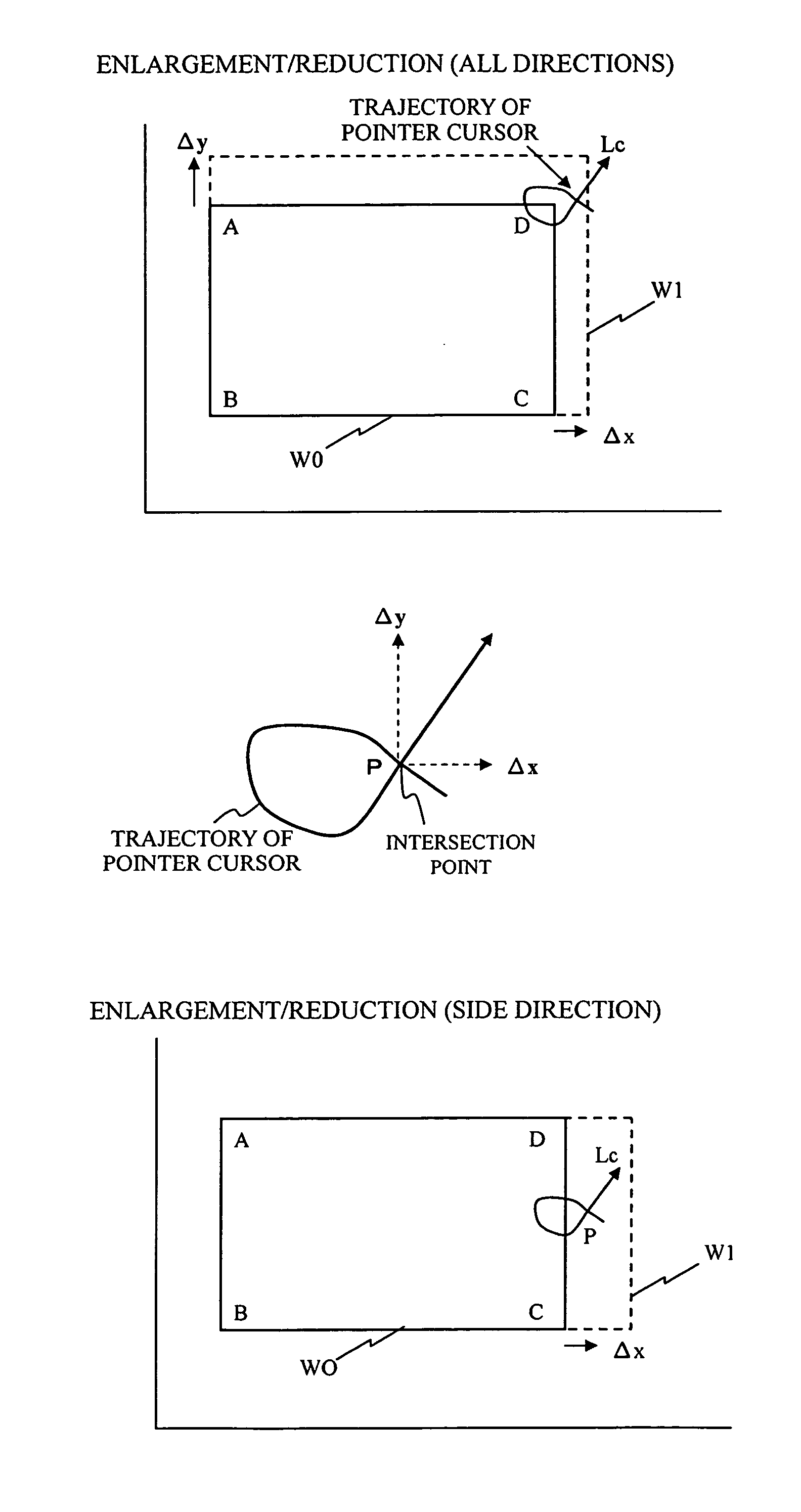
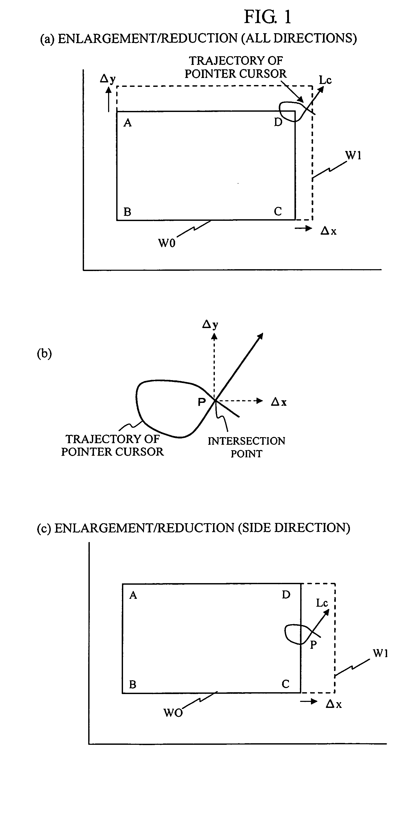
[0018] In accordance with the invention, a pointer of a pointer device capable of designating an arbitrary point on the screen is moved, and a gesturing operation is carried out such that one of the vertexes at the four corners of the window frame, for example, is encircled by the trajectory of the movement, thereby designating the operated object. The operated object is then moved such that the window frame is enlarged or reduced in size in the direction of movement of the pointer by an amount corresponding to the movement. Thus, the need for accurately positioning the pointer cursor at a vertex of the window can be eliminated.
[0020] Thus, the operability during the enlargement / reduction or movement of the window can be improved. In particular, in a system, such as the electronic blackboard system, where the origin of the coordinate system for recognizing the position of the pointer on the screen consisting of a white board tends to become out of alignment with the origin of the projection coordinate system for the projection and display of the window, the invention allows the user to enlarge, reduce or move the window without worrying about the potential misalignment between the projected and displayed pointer cursor and the point position of the pointer device. Thus, the operability during the enlarging, reducing, or moving the window can be improved.

Problems solved by technology

As a result, depending on the manner of alignment, a separate, unintended frame line might be erroneously designated, or an unintended operation might be carried out.
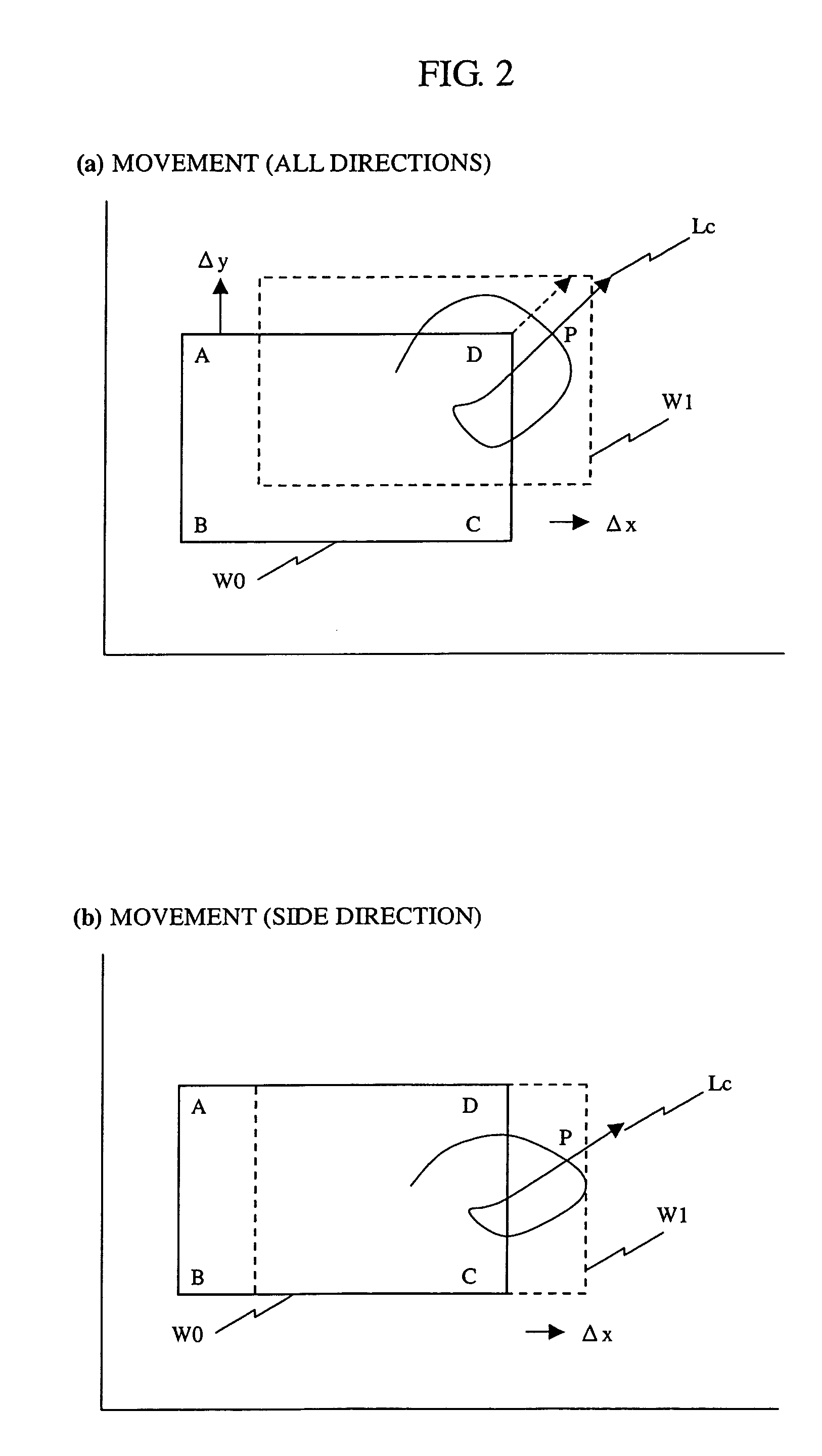
Moreover, the method disclosed in Patent Document 1, which the present inventors have proposed, has the problem that the window frame cannot be moved and that it is not capable of increasing or decreasing the size of a window frame in an opposite angle direction while using an arbitrary vertex thereof as a movable object.

Method used


Image

  • Window control method
  • Window control method
  • Window control method

Examples


Embodiment Construction

[0054] The invention will be described by way of embodiments with reference made to the drawings.

[0055] In accordance with the invention, a pointer cursor of a pointer device capable of designating an arbitrary point on a screen is moved. For example, the cursor is moved to execute a gesturing operation such that one of the four vertexes at the four corners of a window frame is enclosed, thereby designating an operated object based on the trajectory of the movement of the cursor. The operated object can then be moved such that the window frame can be increased or decreased in size in the direction of movement of the operated object by an amount corresponding to the amount of that movement.

[0056] Specifically, a vertex or frame of a window is designated as an operated object when increasing or decreasing the size of a window frame or when moving it on the screen. The vertex or a part of the window frame as the operated object is then encircled by the trajectory of the pointer in a ...


PUM


Abstract

A method allows a window to be enlarged, reduced in size, or moved easily by designating an operated object without performing an operation of accurately positioning a point position at a frame line or vertex as the operated object. The method comprises a step of sequentially acquiring the position of a pointer of said pointer device as said pointer is moved after the movement trajectory of said pointer intersects itself following the start of a pointer moving operation, until said pointer moving operation is completed, and storing the thus acquired positions in a table; a step in which it is determined if a part of the movement trajectory of said pointer that is obtained by connecting the information about the movement positions of said pointer stored in said table intersects any of the frame lines of the window as a controlled object, and if it does, the following factors: a. the number of intersected frame lines of the window; and b. the number of end-point coordinates of the intersected frame lines, in order to determine the movement trajectory of said pointer corresponds to which of the instructions of the enlargement / reduction and movement of the window frame, and the window frame or a vertex is determined as the object of operation; and a step of enlarging, reducing, or moving the window frame or vertex as the object of operation in accordance with the thus recognized instruction, in a positional direction in which the movement operation of said pointer has ended after the movement trajectory of said pointer intersected itself, until the completion of the movement operation, by moving the window frame or vertex in accordance with the amount of movement of said pointer.

Description

BACKGROUND OF THE INVENTION [0001] 1. Field of the Invention [0002] The present invention relates to a window control method whereby a window displayed on a screen can be easily increased or reduced in size or moved by a gesturing operation using a pointer. [0003] 2. Background Art [0004] In some applications for performing operations such as increasing or decreasing the size of a figure or moving it, a rectangular enclosing the figure is displayed and a mark is indicated at a vertex or at the center of a side of the rectangle, or a mark is indicated at a vertex of the figure. When increasing or reducing the size of the figure, or when moving it, a cursor is positioned at these marks by designating the position using a pointer device, and the figure is then dragged in a desired direction. [0005] In many of the window systems, the windows that are displayed are rectangular. By dragging a figure using the pointer device with the cursor positioned at any of the sides of the rectangle, ...

Claims


Application Information

Patent Timeline
Patent Type & Authority Applications(United States)
IPC IPC(8): G06F3/048G09G5/00G06F3/033G06F3/038G06F3/0487G09G5/08G09G5/14G09G5/36
CPCG06F3/0481G06F3/038
Inventor TSUKIORI, MITSUHARU
Owner TSUKIORI MITSUHARU
Learn More