This helps you quickly interpret patents by identifying the three key elements:
Problems solved by technology
Method used
Benefits of technology
Benefits of technology
[0014] An object of the present invention is to provide a refrigerator with an icemaker of an improved structure, in which a dispenser is provided at a height convenient for a user.
[0015] Another object of the present invention is to provide a refrigerator with an icemaker of an improved structure, which can dispense ice to a user at an outside of the refrigerator without opening a door.
Problems solved by technology
However, since the refrigerating chamber is allocated under the freezing chamber, the water dispenser can not, but be provided at a relatively low position.
Moreover, the opening of the door on the freezing chamber for using the ice causes escaping to cold air from the freezing chamber to an outside of the refrigerator, resulting in temperature rise of the freezing chamber, to required more work of the compressor that consumes an energy.
Method used
Image
Click on the blue label to locate the original text in one second.
Reading with bidirectional positioning of images and text.
Examples
fifth embodiment
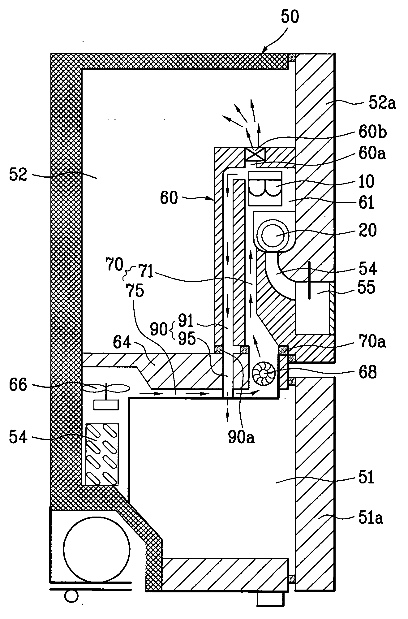
[0087] FIGS. 5 to 10 illustrate the refrigerators of improved structures of the present invention, referring to which the refrigerator of improved structure of the present invention will be described. For reference, FIG. 5 illustrates a diagram of an improved refrigerator in accordance with a preferred embodiment of the present invention, FIGS. 6 to 9 illustrate side sections each showing first to fourth preferred embodiment refrigerator of the refrigerator in FIG. 5 in succession, and FIG. 10 illustrates a front view of the refrigerator in FIG. 5, showing a first and a third ducts.
fourth embodiment
[0088] A common structure for the first to fourth embodiment refrigerators of the present invention will be described, with reference to FIGS. 5˜9.
[0089] Referring to FIGS. 5˜9, there are a freezing chamber 52 in an upper part of the cabinet 50, and a refrigerating chamber 51 in a lower part of the cabinet 50. As shown in FIGS. 6˜9, the refrigerating chamber 52 and the freezing chamber 51 are compartmentalized into independent spaces with a mullion wall 64.
[0090] Referring to FIGS. 6˜9, the freezing chamber 51 is provided with an evaporator 65. There is a fan adjacent to the evaporator 65. According to this, the cold air formed in the vicinity of the evaporator 65 is supplied to the freezing chamber 51 or the refrigerating chamber 52 by the fan 66.
[0091] In the meantime, the evaporator 65 is provided, not only in the freezing chamber 51. That is, though not shown, the evaporator 65 can also be provided to the refrigerating chamber 52. Moreover, a plurality of the evaporators 65 ma...
second embodiment
[0120] Referring to FIG. 7, in the second embodiment, the hole 81 has louvers 85, additionally. The louver 85 controls a discharge direction of the cold air supplied to the refrigerating chamber 52 through the holes 81. Therefore, once the louver 85 is provided, the cold air can be supplied to every part of the refrigerating chamber 52, more effectively.
[0121] In the meantime, in the second embodiment refrigerator, there may be a damper 67 provided thereto for controlling an amount of cold air supplied to the second duct 80. As shown in FIG. 7, the damper 67, provided to an end of the second duct 80, for opening / closing or controlling opening of the one end of the second duct 80. Once the damper 67 is provided thus, the cold air supply to the refrigerating chamber 52 can be stopped when the temperature of the refrigerating chamber 52 is low.
[0122] A process for supplying cold air in the refrigerator in accordance with the second preferred embodiment of the present invention having ...
PUM
Abstract
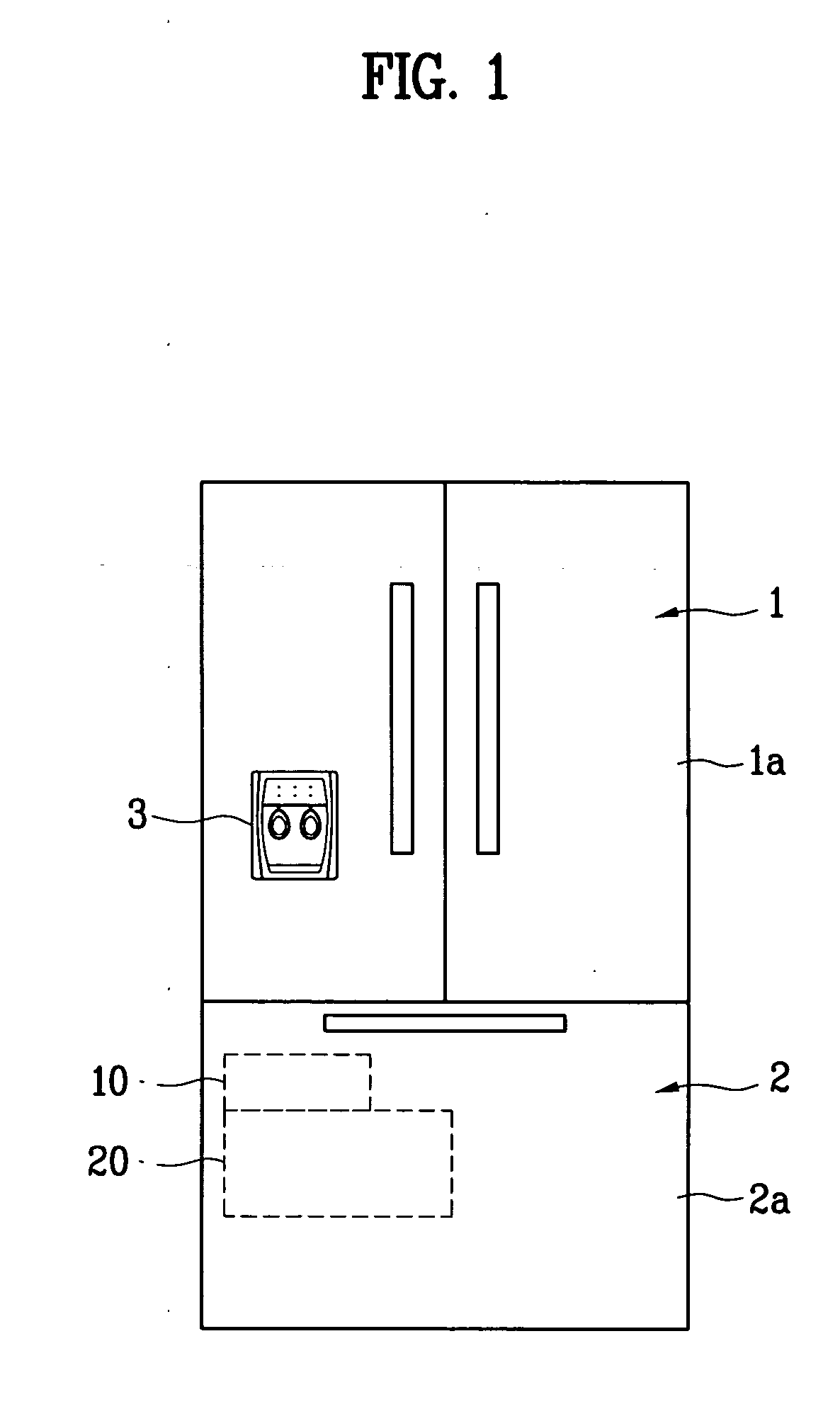
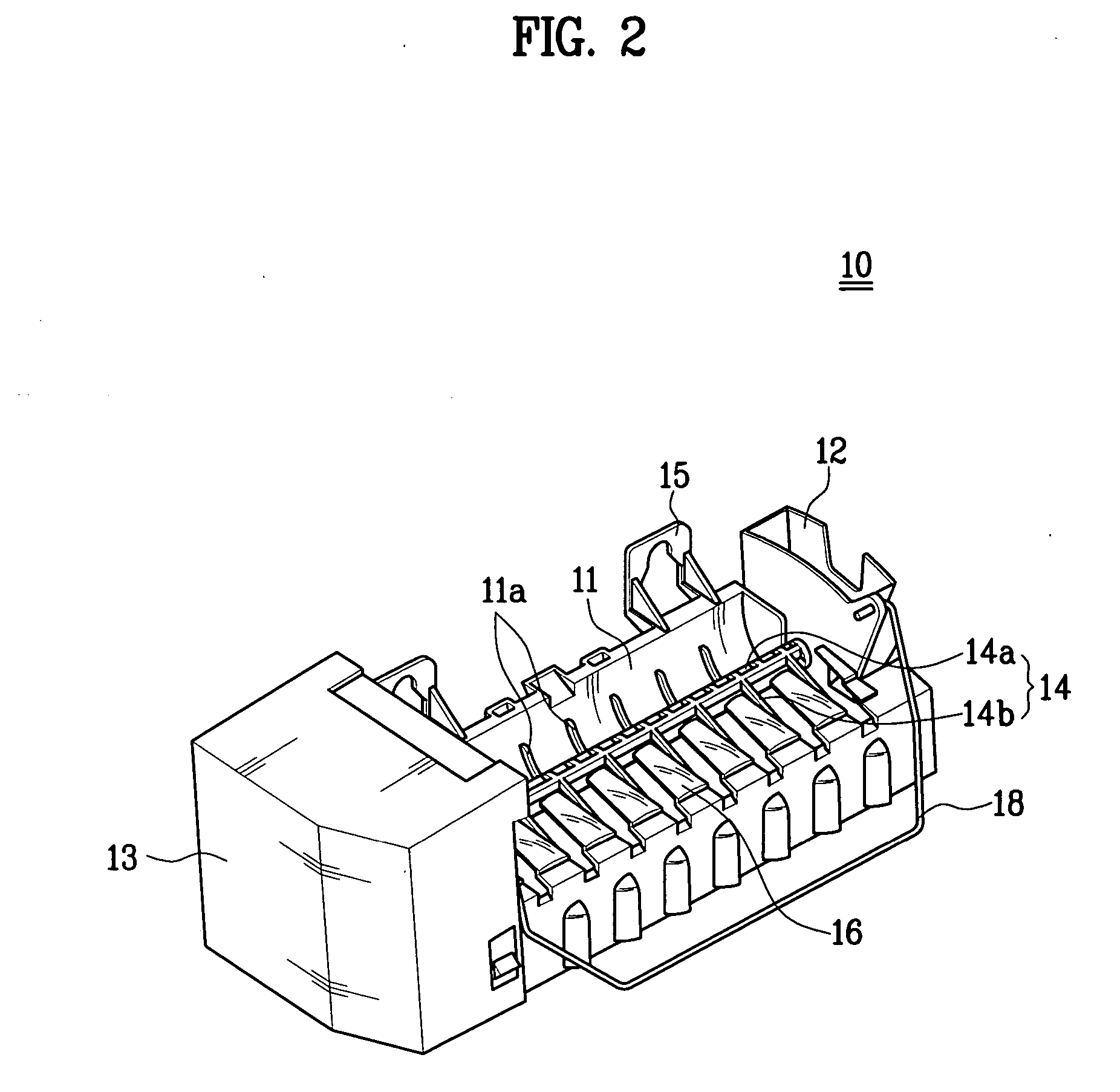
Refrigerator with an icemaker including a cabinet having a mullion wall for compartmentalization of a freezing chamber and a refrigerating chamber, a case provided to a door on the refrigerating chamber, having a cavity therein, a first duct for supplying cold air from a neighborhood of an evaporator in the freezing chamber to the cavity, the icemaker in the cavity for producing ice, an ice container in the cavity for storing the ice, and a dispenser in the door in communication with the cavity, thereby having ice supplied to a user at an outside of the refrigerator through a dispenser provided to the door.
Description
[0001] This application claims the benefit of the Korean Application No. P2003-0065163 filed on Sep. 19, 2003, which is hereby incorporated by reference. BACKGROUND OF THE INVENTION [0002] 1. Field of the Invention [0003] The present invention relates to refrigerators, and more particularly, to a refrigerator with an icemaker of an improved structure, which can dispense ice pieces from a dispenser provided to a refrigerator door. [0004] 2. Background of Related Art [0005] The refrigerator is used for long time fresh storage of food. The refrigerator has food storage chambers each of which temperature is maintained in a low temperature state by a refrigerating cycle, for fresh storage of the food. [0006] There are a plurality of storage chambers of different characteristics, so that the user can select storage methods suitable for storage of various kinds of food, taking kinds and characteristics of food and required storage time periods into account. Of the storage chambers, the ref...
Claims
Application Information
Patent Timeline
Application Date:The date an application was filed.
Publication Date:The date a patent or application was officially published.
First Publication Date:The earliest publication date of a patent with the same application number.
Issue Date:Publication date of the patent grant document.
PCT Entry Date:The Entry date of PCT National Phase.
Estimated Expiry Date:The statutory expiry date of a patent right according to the Patent Law, and it is the longest term of protection that the patent right can achieve without the termination of the patent right due to other reasons(Term extension factor has been taken into account ).
Invalid Date:Actual expiry date is based on effective date or publication date of legal transaction data of invalid patent.

