3-action lock barrel

a technology of lock barrel and lock lock, which is applied in the direction of cylinder locks, building locks, construction, etc., can solve the problems of poor protection of burglarproof lock sets, and achieve the effect of effectively preventing unauthorized unlocking

Inactive Publication Date: 2005-03-24
LIN BOR CHING
View PDF11 Cites 18 Cited by
  • Summary
  • Abstract
  • Description
  • Claims
  • Application Information

AI Technical Summary

Benefits of technology

[0005] The primary purpose of the present invention is to provide a three-action lock barrel to upgrade identification function. The two-action lock barrel used in a prior art of lockset involves insertion of the key into the rotor, separation of the rotor from the case of the locking pins and turning the key to unlock (two-action relation). Those locking pins longitudinally move on Y-axis indicating its function being related to one-dimension operation. The present invention involves insertion of the key into the rotor, turning around the locking pins (two-action relation), separation of the locking pins from the case to turn the key to unlock (three-action relation). Wherein, the locking pins also longitudinally move along Y-axis; the variation of the thickness among the locking pins takes place on the horizontal X-axis indicating a function of two-dimensional operation. That is, the turning axis of the barrel is related to Variance 1; the longitudinal movement of the locking pin along Y-axis (vertical direction) is related to Variance 2; and the width of the locking pin on X-axis (horizontal direction) is related to the variance depending on the changes of the locking pin movement on X-axis and Y-axis. The present invention by upgrading identification factor from the one-dimensional operation space of the locking pin (up and down) to two-dimensional operation space effectively prevents unauthorized unlocking to maintain the function of the lockset.

Problems solved by technology

Therefore, the burglarproof lockset has poor protection results as expected.

Method used


Image

  • 3-action lock barrel
  • 3-action lock barrel
  • 3-action lock barrel

Examples


Embodiment Construction

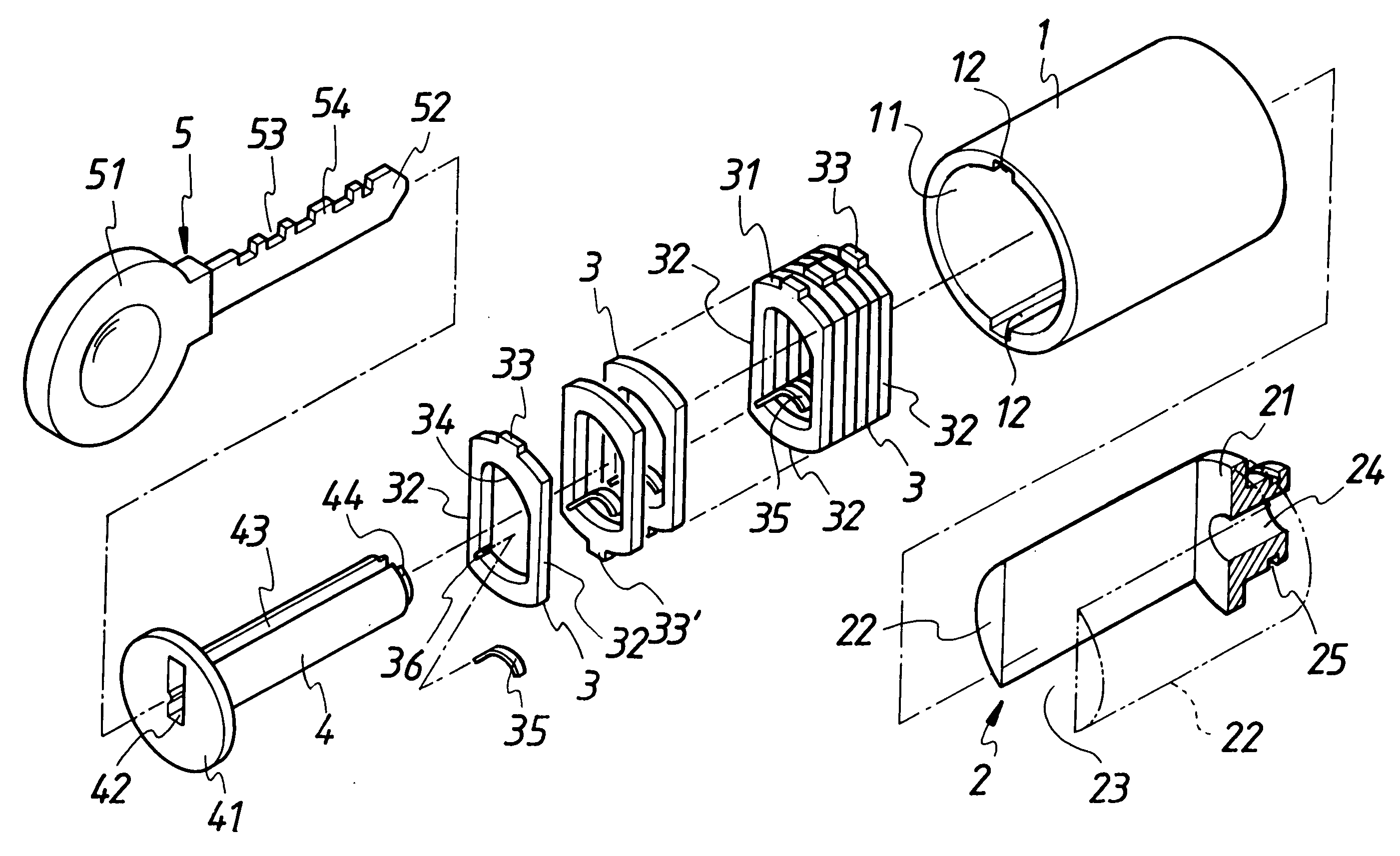
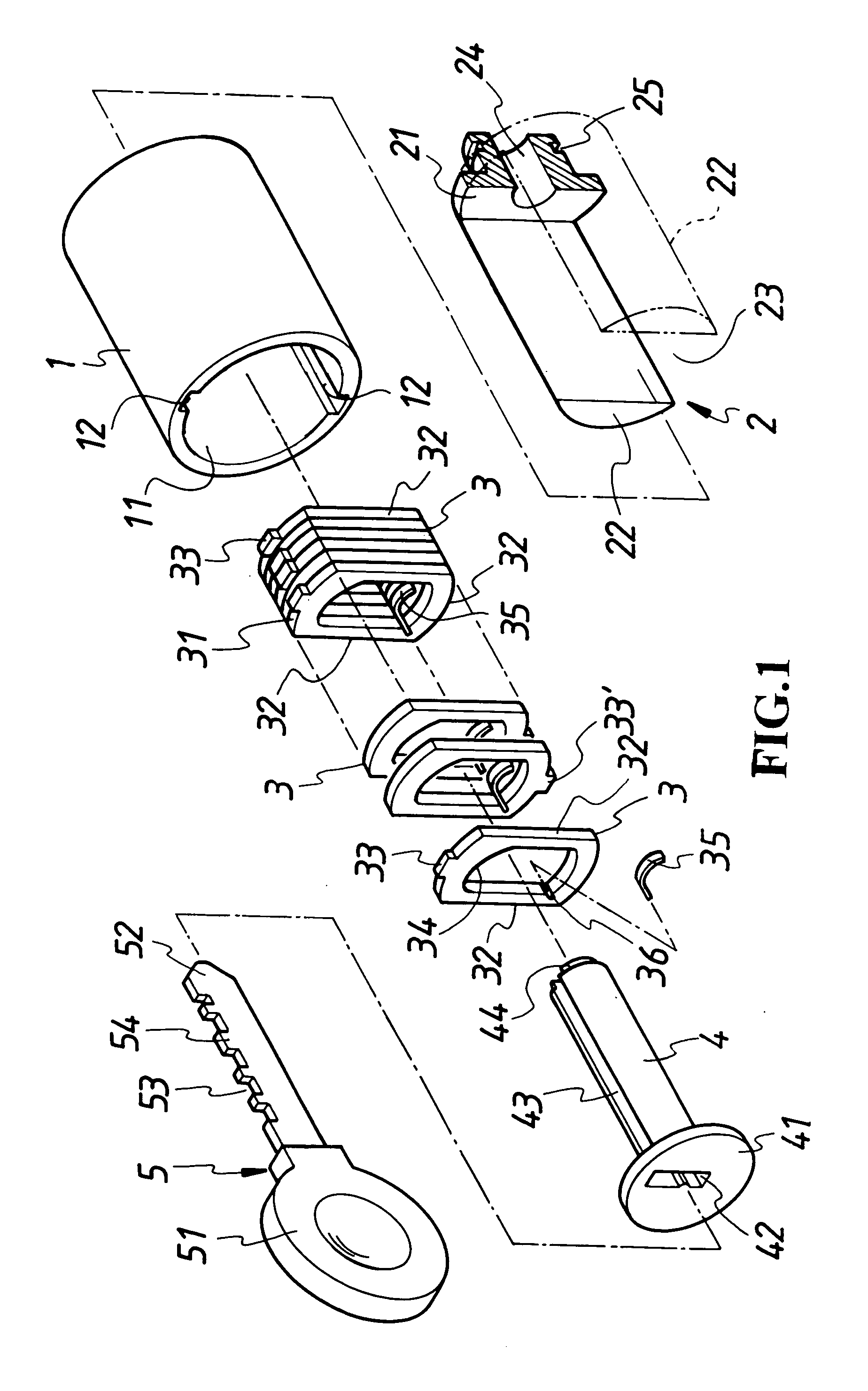
[0020] As illustrated in FIG. 1, a three-action lock barrel for a lockset includes a case 1, a limiter 2, multiple locking plates 3 and a rotor 4 adapted with a key 5 to unlock. Wherein, the case 1 related to a hollow cylinder mounted to a burglarproof lockset has at its middle provided with a circular hole 11 to accommodate the limiter 2, those multiple locking plates 3 and the rotor 4, and at two selected relative locations on the inner wall of the circular hole 11 respectively provided with a groove 12 extending axially.

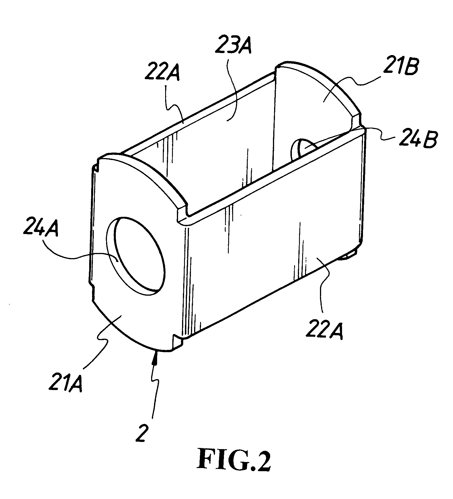
[0021] The limiter 2 mounted inside the case 1 has on its both sides respectively provided with a limiting plate 22 (22A), to define a room 23 (23A) formed with a longitudinal open space to accommodate and limit (guide) those multiple locking plates 3 arranged in flush to engage longitudinal sliding movement as illustrated in FIG. 1. The limiter 2 can be driven to rotate to unlock and substantially formed in a structure having both sides at the front end of a cir...


PUM


Abstract

A three-action lock barrel having collective locking pins and two-way locking up mechanism is comprised of a case, a limiter, multiple locking plates and a rotor; the case being related to a hollow cylinder; a trough axially extending each from the inner wall of the case; the limiter being provided to limit the longitudinal sliding movement of those multiple locking plates arranged in flush and abutted to one another and accommodated inside the limiter; each locking plate being provided with an upper or a lower locking pin selected at random; the rotor receiving insertion of a key; the key turns around to push those locking pins to clear away or insert into a groove.

Description

BACKGROUND OF THE INVENTION [0001] (a) Field of the Invention [0002] The present invention is related to a 3-action lock barrel, and more particularly, to one that is adaptable to various types of burglarproof lockset. [0003] (b) Description of the Prior Art [0004] The prior art of the lock barrel for a burglarproof lockset is generally comprised of a rotor, a case, a row or multiple rows of locking pins and spring. Wherein, the rotor is inserted into the case, one row or multiple rows of radial through holes is provided respectively to the rotor and the case for the upper and the lower locking pins to be respectively inserted into each through hole; and a compression spring is provided at the top of the upper locking pin, All the upper and the lower locking pins are restricted at where between the rotor and the case to prevent the barrel from being turned around. To unlock, a key is required to insert into a keyhole of the rotor to push those lower and upper locking pins to slide u...

Claims


Application Information

Patent Timeline
Patent Type & Authority Applications(United States)
IPC IPC(8): E05B27/00E05B29/00E05B29/04
CPCE05B21/063Y10T70/7531Y10T70/7599Y10T70/7695Y10T70/7785
Inventor LIN, BOR CHING
Owner LIN BOR CHING
Why Eureka
Try Eureka