Rechargeable LED lighting and flashing apparatus

Inactive Publication Date: 2005-03-24
NIEMANN BRADLEY Q
View PDF2 Cites 50 Cited by
  • Summary
  • Abstract
  • Description
  • Claims
  • Application Information

AI Technical Summary

Problems solved by technology

However, the rechargeable batteries normally required a

Method used


Image

  • Rechargeable LED lighting and flashing apparatus
  • Rechargeable LED lighting and flashing apparatus
  • Rechargeable LED lighting and flashing apparatus

Examples


Embodiment Construction

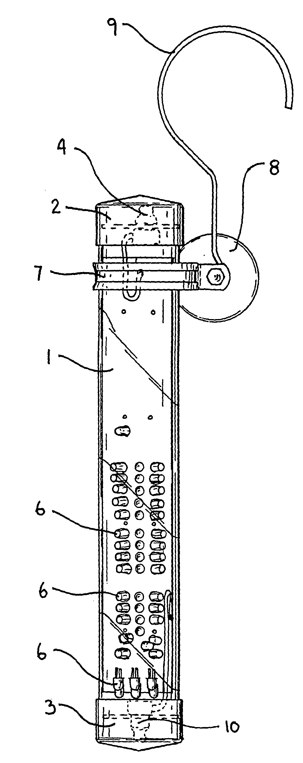
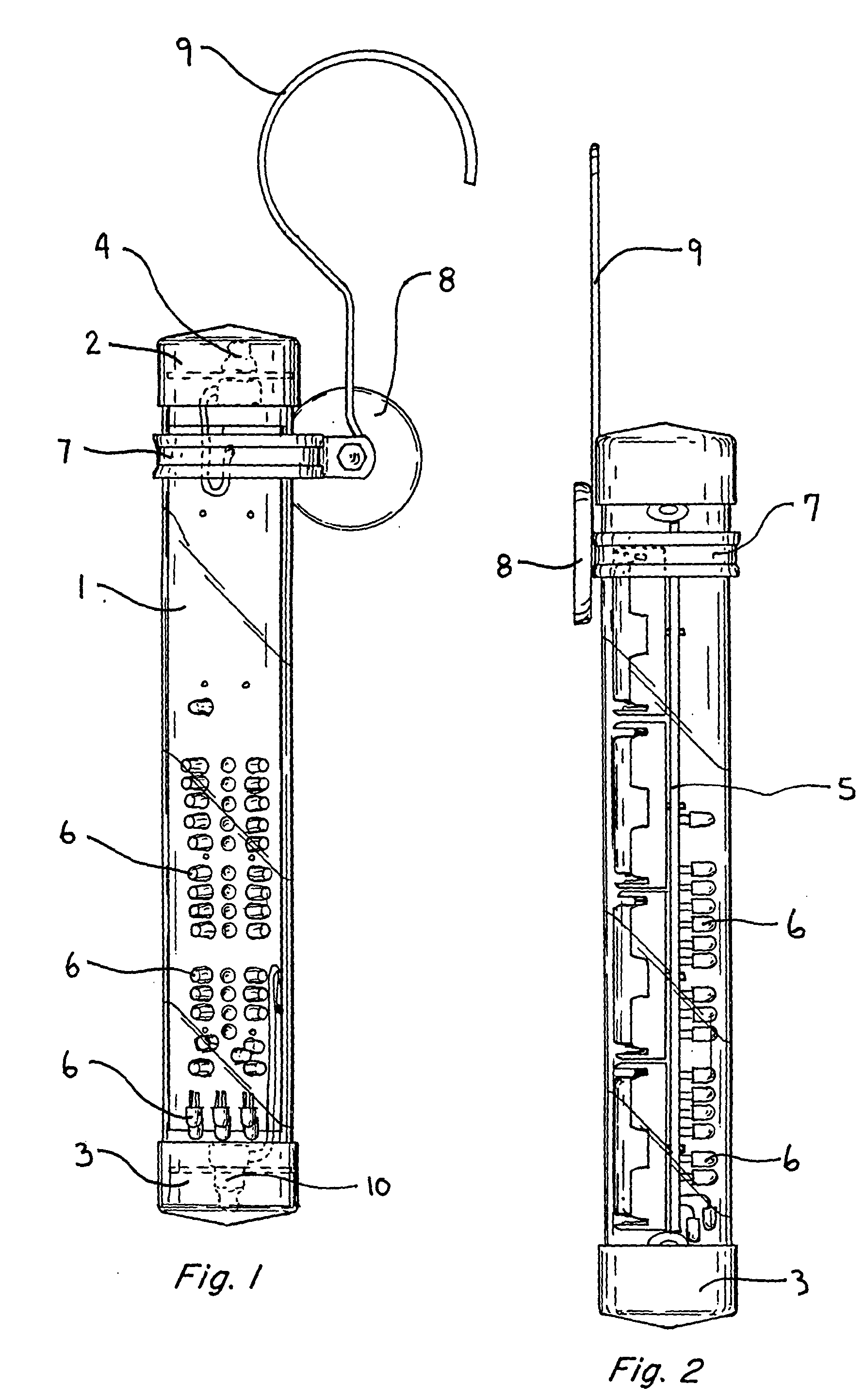
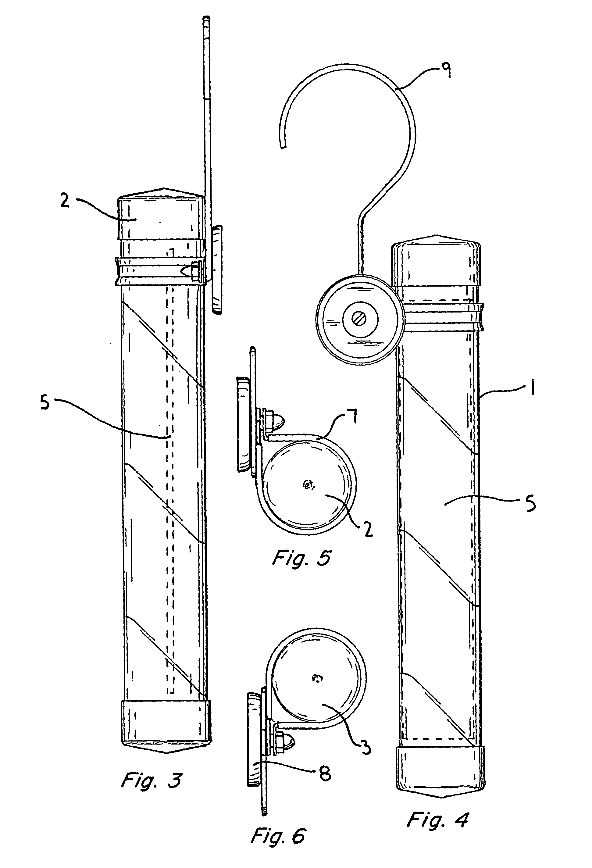
[0014] A rechargeable LED lighting and flashing apparatus has an elongated, clear, hollow cylindrical body 1. The body is generally in the shape of a cylinder, having a circular cross section. However, it is to be appreciated that this particular light may take a different shape or may have a square or rectangular cross section. The clear cylindrical body 1 is generally made of hard plastic or other clear, durable material. The cylindrical body has a flexible removable top cap 2 and a flexible bottom cap 3. These caps are removable so as to allow the user access to the top 4 and bottom 10 switches of the device.

[0015] Inside the cylindrical body 1 is a standard circuit board 5. This circuit board is shown in dotted lines in FIGS. 3 and 4. The internal circuit board is fixed inside of the cylindrical body 1 and contains a number of light emitting diodes (LEDs) 6. Generally, these LEDs are located as in FIGS. 1 and 2. Any number of LEDs may be utilized in practicing this invention. H...


PUM


Abstract

A clear, hollow cylindrical tube having an internal circuit board with LED lights provides a lighting and flashing illumination device. The LED lights may either all be illuminated at once, or have certain LEDs with constant illumination while other LEDs may be placed into a flashing mode. The power source for the lighting and flashing apparatus includes either standard or rechargeable batteries and a 12-volt external source. The 12-volt external source may also be used to recharge the rechargeable batteries. The cylinder has an upper collar with both magnetic and hook hanging mechanisms. The rechargeable LED lighting and flashing apparatus provides much more illumination than a flashlight using standard charging and lighting electrical parts.

Description

BACKGROUND OF THE INVENTION [0001] This invention relates to the field of illumination devices. More particularly, a unique rechargeable LED lighting and flashing apparatus is presented which provides much more light than the usual flashlight and which also has a flashing feature. [0002] Many improvements have been made in the field of lighting over the centuries. From lighting by fire, to torches, to gas lights, to automobile and battery-powered lights, many new innovations have adapted the current technology to the need to provide lighting at remote or inaccessible locations. The common flashlight was devised to provide a portable source of light using standard batteries. [0003] Improvements to the standard flashlight have also included rechargeable batteries, flashing circuitry, and different types and sizes of flashlights as well as other portable illumination devises. With the invention of LEDs (light emitting diodes) a new means to provide illumination has been made available....

Claims


Application Information

Patent Timeline
IPC IPC(8): F21L4/02F21L4/08F21V21/096F21V23/04
CPCF21L4/027F21L4/085F21Y2101/02F21V23/0407F21V23/0414F21V21/0965F21Y2115/10
Inventor NIEMANN, BRADLEY Q.
Owner NIEMANN BRADLEY Q
Why Eureka
Try Eureka