System uses internet electronic mail for requesting status of a monitored device from a monitoring device

a technology of monitoring device and internet electronic mail, which is applied in the field of remote monitoring, diagnosis and control of machines, can solve problems such as inappropriate connectionless communication, and achieve the effect of quick and efficient access to information

Inactive Publication Date: 2005-03-24
RICOH AMERICAS CORP
View PDF28 Cites 40 Cited by
  • Summary
  • Abstract
  • Description
  • Claims
  • Application Information

AI Technical Summary

Benefits of technology

[0012] The invention additionally includes a data base having information of the machine(s) including information of the model, configuration, and capability of the machine(s) so that the remote station will know the machine's capabilities. The data base is shared among different groups such as between a service group, a marketing group, a manufacturing group and an engineering group in order to have quick and efficient access to information regarding the operating characteristics and reliability of the machines.

Problems solved by technology

When a condition exists within the machine which needs urgent attention, a connectionless-mode of communication may be inappropriate.

Method used


Image

  • System uses internet electronic mail for requesting status of a monitored device from a monitoring device
  • System uses internet electronic mail for requesting status of a monitored device from a monitoring device
  • System uses internet electronic mail for requesting status of a monitored device from a monitoring device

Examples


Embodiment Construction

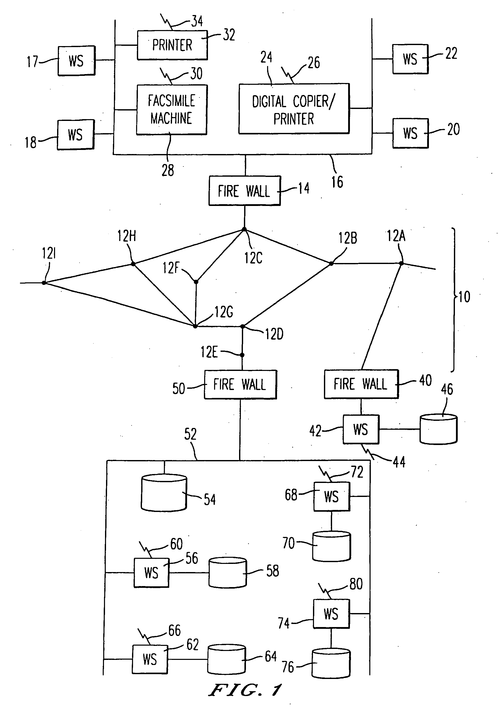
[0028] Referring now to the drawings, wherein like numerals designate identical or corresponding parts throughout the several views, and more particularly to FIG. 1 thereof, there is illustrated a figure showing various machines and computers for monitoring, diagnosing and controlling the operation of the machines. In FIG. 1, there is a first network 16, such as a Local Area Network (LAN) connected to computer workstations 16, 18, 20 and 22. The workstations can be any type of computers including IBM Personal Computer compatible devices, Unix Based Computers, or Apple Macintoshes. Also connected to the network 16 are a digital copier / printer 24, a facsimile machine 28, and a printer 32. The devices 24, 28 and 32 are referred to as machines or monitored devices although other types of devices may be used as the machines or monitored devices. Also, a facsimile server (not illustrated) may be connected to the network 16 and have a telephone or ISDN connection. In addition to the digita...


PUM


Abstract

A method and system for monitoring, controlling and diagnosing operation of a machine such as a business office machine including a facsimile machine, a copier, and a printer. When the speed of communication between the remote device and machine is not urgent, a connectionless mode of communication may be used. The form of connectionless communication is an electronic mail message transmitted over the Internet. However, when a condition needs urgent action, a direct connection is used for communication such as communication via a telephone or ISDN line. The information obtained from the machine is stored in one or more data bases within a company and information of the machine is shared between a service department, engineering and design department, manufacturing department, and marketing department. As communication over the Internet via electronic mail is not secure, the connectionless-mode messages transmitted using Internet electronic mail are encrypted.

Description

CROSS-REFERENCES TO RELATED APPLICATIONS [0001] The present application is related to U.S. patent application Ser. No. 08 / 426,679 filed Apr. 24, 1995 and entitled “Method and Apparatus for Controlling and Communicating With Business Office Devices” which is a continuation of U.S. patent application Ser. No. 08 / 282,168 filed Jul. 28, 1994 and entitled “Method and Apparatus for Controlling and Communicating With Business Office Devices”, now U.S. Pat. No. 5,412,779, which is a continuation of U.S. patent application Ser. No. 07 / 902,462 filed Jun. 19, 1992, now abandoned, which is a continuation of U.S. patent application Ser. No. 07 / 549,278, filed July 6, 1990, now abandoned, the disclosure of each is incorporated herein by reference.BACKGROUND OF THE INVENTION [0002] 1. Field of the Invention [0003] The present invention is related to the remote monitoring, diagnosis and control of machines using connection- and connectionless-modes of communication and is more particularly related t...

Claims


Application Information

Patent Timeline
Patent Type & Authority Applications(United States)
IPC IPC(8): G03G21/00G03G15/00H04L12/26H04L12/28H04L12/58H04L29/06H04L29/08H04M11/00H04N1/00H04N1/32
CPCG03G2215/00109G03G15/5079H04L12/2602H04L12/5692H04L12/58H04L12/5875H04L43/00H04L43/06H04L43/065H04L43/0817H04L43/12H04L43/16H04L63/02H04L63/029H04L63/0428H04L63/1408H04N1/00002H04N1/00007H04N1/00029H04N1/00079H04N1/00209H04N1/00281H04N1/00312H04N1/33323H04N1/44H04N2201/0039H04N2201/0094H04N2201/33342H04L67/125H04L67/02H04L69/329G06F2221/2105H04L51/00H04L51/23
Inventor MOTOYAMA, TETSURO
Owner RICOH AMERICAS CORP
Why Eureka
Try Eureka