
Image forming apparatus

a technology of forming apparatus and toner, which is applied in the direction of electrographic process apparatus, instruments, optics, etc., can solve the problems of large deformation of toner density, large time-consuming and laborious replenishment of toner, and fluctuation of density of developed toner images, so as to achieve proper and stable transition of toner replenishment amount, density transition and stability

Inactive Publication Date: 2005-03-24
CANON KK
View PDF8 Cites 5 Cited by
  • Summary
  • Abstract
  • Description
  • Claims
  • Application Information

AI Technical Summary

Benefits of technology

[0015] It is therefore an object of the present invention to ensure a proper density transition and stability by gaining a proper and stable transition of a toner replenishment amount.

Problems solved by technology

Even when the toner-to-carrier ratio of the developer is thus kept fixed, there is still a case where the density of a developed toner image might fluctuate due to deterioration of the carrier, an environmental change, a change in image of an original, etc.
H09-022179, however, it takes much time for the replenished toner to reach the toner density detection means 7 in the developing device, and consequently the toner replenishment amount has a ripple as shown in FIG. 12, with the result that the toner density largely deflects.
When the image density is switched over, the toner replenishment amount changes, thereby causing a much larger ripple.
Further, even if noises enter the result of the detection by the toner density detection means 7 due to a developer volume density deflection, a contamination on the toner density detection means 7, etc, the toner replenishment amount becomes improper.
H09-127780, the above ripple can be slightly reduced by replenishing the toner on the basis of a result of the video counter count, however, a degree of this reduction was not sufficient.

Method used


Image

  • Image forming apparatus
  • Image forming apparatus
  • Image forming apparatus

Examples


first embodiment

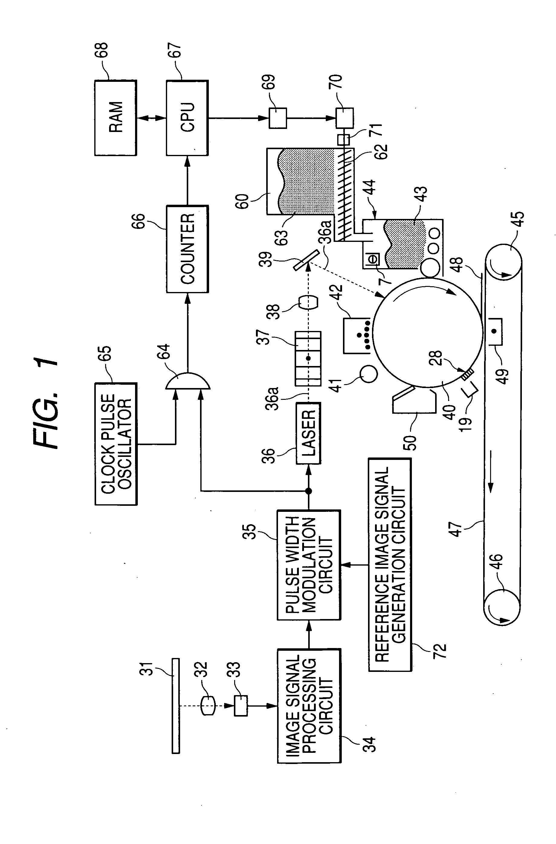
[0031]FIG. 1 is a schematic view of an electrophotographic type digital copying machine defined as an image forming apparatus using a developing apparatus in an embodiment of the present invention.

[0032] In the electrophotographic type digital copying machine, an image of an original 31 that should be copied is projected through a lens 32 on an image sensing element 33 such as a CCD, etc. The image sensing element 33 separates the image of the original into a multiplicity of pixels, and generates optical converting signals corresponding to densities of the respective pixels. Analog image signals outputted from the image sensing element 33 are transmitted to an image signal processing circuit 34. The image signal processing circuit 34 converts the analog image signals into pixel image signals having output levels corresponding to the densities of the pixels on a pixel-by-pixel basis, and the thus-converted pixel image signals are transmitted to a pulse width modulation circuit 35.

[...

second embodiment

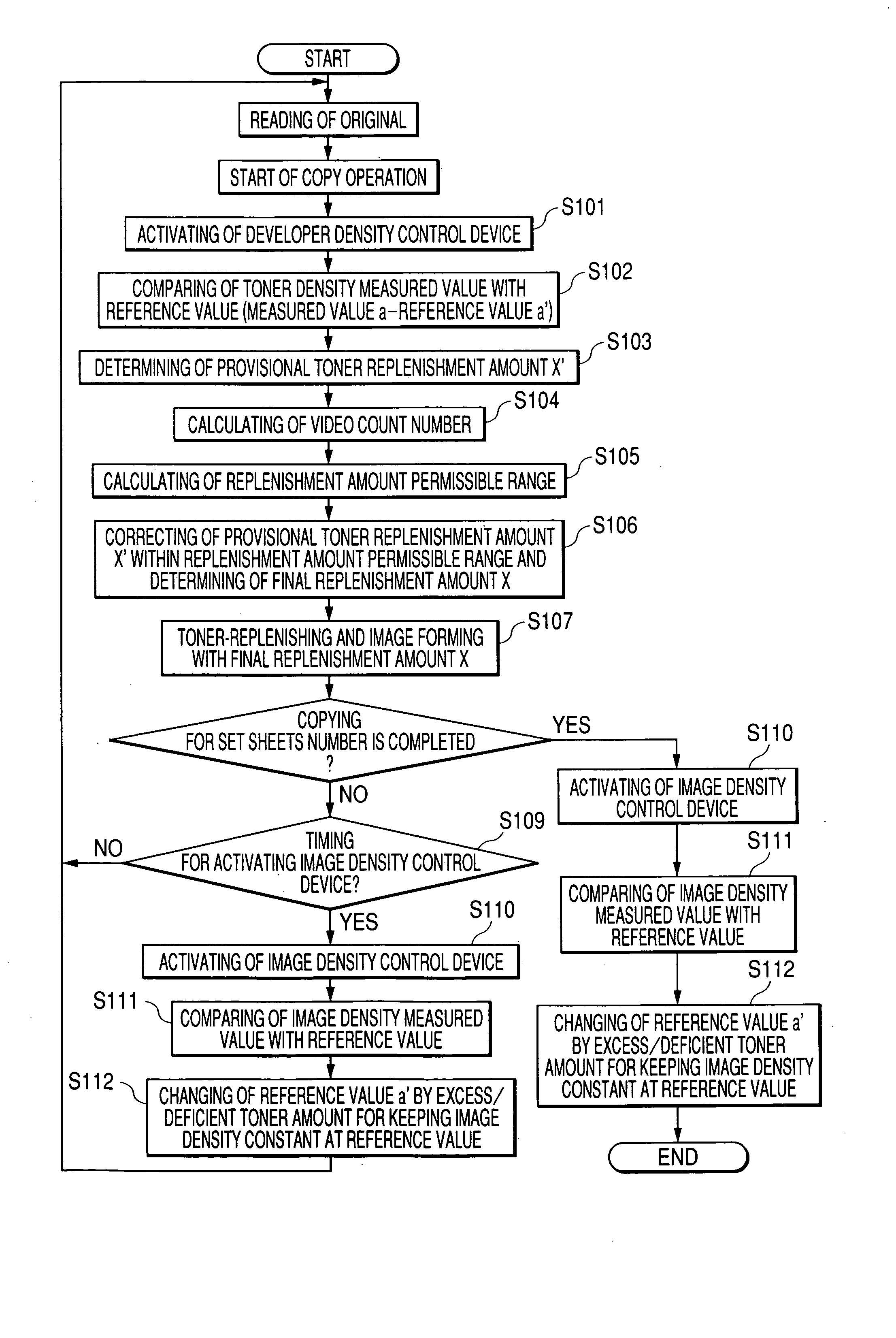
[0082] A second embodiment is an exemplification in which the control for changing the target value of the toner density under the patch detection ATR is contrived more suitably for the present invention.

[0083] In the case of the control exemplified in the first embodiment, when continuing to detect that the density on the photosensitive drum 40 is thin, the target value of the toner density rises continuously. As a result of this, the toner replenishment amount increases but is not beyond the replenishment amount permissible range shown in FIG. 8. Therefore, when frequently activating the patch detection ATR and so on, the target value of the toner density rises, however, there occurs a state where the actual toner density does not increase so much. Next, when detecting that the density on the photosensitive drum 40 is thick, the toner target density decreases. Since the target value of the toner density excessively rises, however, the toner target density, even though decreased, ...

third embodiment

[0088] A third embodiment is an exemplification of modifying (improving) inconvenience caused due to the use with a delay by one sheet since the signal from the video count C1 does not catch up with.

[0089] After reading an original 31, as described above, the original signal is converted into the laser drive signal by use of the image signal processing circuit 34 and the pulse width modulation circuit 35. After all the conversions for the target original 31 have been finished, a calculation value is obtained by the counter 66. The signals are, however, sequentially transmitted to the laser 36 while performing the conversions, thus forming the image. Therefore, almost simultaneously with the end of the image formation involving the use of the laser 36, the calculation value by the counter 66 is obtained. Accordingly, when the present invention is applied, the replenishment amount permissible range acquired by performing the calculation from the video counter C1 is employed for the n...


PUM


Abstract

An image forming apparatus includes a latent image forming portion for forming an electrostatic latent image corresponding to image information on an image bearing member, a developing portion, having a developer container for accommodating a developer containing a toner and a carrier, for developing the electrostatic latent image with the toner, and a toner density detecting portion for detecting a toner density in the developer container, a toner replenishment amount to the developer container being controlled in accordance with a result of detection by the toner density detecting portion, wherein a toner replenishment amount target value used for controlling the toner replenishment is controlled to fall within a restriction range, and the restriction range can be changed according to the image information.

Description

BACKGROUND OF THE INVENTION [0001] 1. Field of the Invention [0002] The present invention relates to an image forming apparatus utilized for a copying machine, a printer, FAX, etc. that involve using an electrophotographic system. [0003] 2. Related Background Art [0004]FIG. 11 shows one example of the image forming apparatus. [0005] There has been provided the image forming apparatus, wherein a developer supplied onto the surface of a developing sleeve 3 defined as a developer carrying member by developer agitation carrying means 11, 12, is held in a magnetic bead chain state by a magnetic force of a magnet roller 13, and is carried to a developing area of an opposite portion facing a photosensitive drum 40 defined as an image bearing member on the basis of a rotation of the developing sleeve 3, and the magnetic bread chain is scraped off by a return member 1 defined as a developer stay amount regulating member for regulating an amount of developer staying on the developing sleeve a...

Claims


Application Information

Patent Timeline
Patent Type & Authority Applications(United States)
IPC IPC(8): G03G15/00G03G15/08
CPCG03G2215/00042G03G2215/0685G03G2215/0888G03G15/0893G03G15/0849G03G15/0853G03G15/0877
Inventor FUJIWARA, MOTOHIRO
Owner CANON KK
Learn More